
Related Manuals for Still EK-X


Summary of Contents for Still EK-X
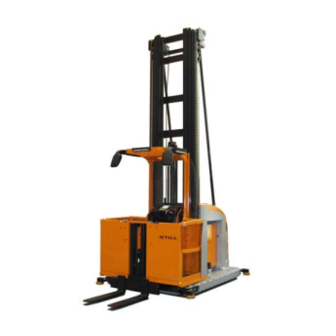
- Page 1 Original instructions High level order picker EK-X 2131 2133 5213 804 2501 EN - 01/2016...
-
Page 3: Table Of Contents
Table of contents Foreword General ............2 EC declaration of conformity . - Page 4 Table of contents Overview View of the truck ........... . . 26 Labelling on standard trucks .
- Page 5 Table of contents Parking, decommissioning ..........69 Parking and leaving the truck .
-
Page 7: Foreword
Foreword... -
Page 8: General
Foreword General General Our industrial trucks comply with applicable European regulations. Any other applicable country-specific regulations or operating conditions for the use of industrial trucks must also be observed. The aim of this manual is to inform you about how to safely handle your industrial truck and how to keep it operational. -
Page 9: Ec Declaration Of Conformity
Foreword EC declaration of conformity EC declaration of conformity Declaration STILL GmbH Berzeliusstraße 10 D-22113 Hamburg Germany We declare that the according to these operating instructions Industrial truck according to these operating instructions Model conforms to the latest version of the Machinery Directive 2006/42/EC. -
Page 10: Safety Instructions
Foreword Safety instructions Safety instructions Explanations of the terms used in this manual: DANGER There is the risk of fatality to the operator. The procedures indicated should be complied with in full in order to avoid this danger. WARNING There is a hazard that could cause major damage to property or to the health of the operator. -
Page 11: Truck Identification, Factory Nameplate
Foreword Truck identification, Factory nameplate Truck identification, Factory nameplate The nameplate is fitted in the area of the driving seat and contains the following details: Factory nameplate CE symbol. The CE symbol confirms that Nominal loading capacity the EU machine guidelines and all the Unladen weight relevant guidelines, which are valid for this Battery voltage... -
Page 12: Product Support Documentation
Foreword Product support documentation Product support documenta- tion This includes: • Spare parts list • Operating and maintenance manual • VDMA (German Engineering Federation) information booklet on proper usage • Any additional documentation for the driver’s seat • Any additional documentation for an attach- ment •... -
Page 13: Safe-Keeping And Passing On
Foreword Safe-keeping and passing on Safe-keeping and passing on • These operating and maintenance instruc- tions must be kept safely so that the opera- tor always has access to them. • Documents can be ordered retrospectively. Please give the ID or the order number. •... - Page 14 Foreword Operator, form of address • The ergonomic conditions may be less favourable. For example, it may not be possible to reach pedals such as the accelerator and brake pedals, the overhead guards might be too low or the adjustment ranges for the steering wheel and seat may no longer be sufficient.
-
Page 15: Safety
Safety... -
Page 16: General Safety Information
Safety General safety information General safety information • People must stay away from the working area (danger area) of the truck. If a person does enter the danger area, all movements of the truck must be stopped immediately and the person must be directed away from the area. -
Page 17: General Safety Information
Safety General safety information General safety information • Essentially, all safety information located on the truck must be observed. • Missing or illegible safety information is to be changed. • When cornering and driving past parts of buildings that restrict visibility, use the horn to warn others that the truck is approaching. -
Page 18: Non-Ionising Radiation
Safety Non-ionising radiation Non-ionising radiation WARNING Risk of injury Persons with active or non-active medically implan- ted devices must take it upon themselves to ensure that they are not exposed to dangerous electroma- gnetic radiation. The table below indicates the limit values for the maximum electric field strength of the electromagnetic radiation emitted by this truck. - Page 19 Safety Vibrations accordance with the Directive 2002/44/EC by the operating company at the actual place of use, in order to consider all additional influences, such as driving route, intensity of use etc. 5213 804 2501 EN - 01/2016...
-
Page 20: Special Safety Advices For Engaging Loads
Safety Special safety advices for engaging loads Special safety advices for engaging loads Discuss this with your contractor. Recognising danger is half the battle! • Loads consisting of loose packaged items must not be higher than the upper edge of the cab parapet. -
Page 21: Safe Handling Of Operating Media
Safety Safe handling of operating media Safe handling of operating media The following operating media are used in this truck: • Gear oill • Hydraulic oil • Battery acid The handling of these materials is governed by comprehensive safety regulations. The most important points include: For gear and hydraulic oil DANGER... -
Page 22: Risk Assessment
DANGER Danger of explosion – When charging batteries, an explosive gas mixture can be generated which can still remain present for a long period after completion of the charging process. Ensure adequate ventilation. – Within a 2 metre area of charged batteries, smoking, fires and open flames are strictly... -
Page 23: Regular Testing
Safety Regular testing Regular testing This industrial truck must be checked at least once a year by a specialist (expert) according to our specifications. Our test instructions summarise all activities that must be performed for the purposes of detecting damage or defects that have an effect on safety. -
Page 24: Residual Hazards With Commissioner Trucks
Safety Residual hazards with commissioner trucks Residual hazards with commissioner trucks DANGER Risk of accident – During driving, the operator must make sure that all body parts are located within the truck contour at all times, particularly in trucks without barriers and a cab rail. -
Page 25: Application Area
Safety Application area Application area The floor in the application area must have sufficient strength to bear the weight of the truck. The wheel loads / floor loads specific to your truck will be made available by your responsible sales representative. The condition of the floor surface affects the braking distance of the truck. -
Page 26: Intended Use
Safety Intended use Intended use These industrial trucks are intended for use in order picking applications, i.e. for collecting parts that are stored in racking systems, for example. This industrial truck is therefore designated as a vertical order picker. The forks must be equipped with suitable load-carrying equipment in order to set down the parts picked for the order. -
Page 27: Narrow Aisle Vehicles
Safety Narrow aisle vehicles Engineering Federation) and therefore need to be converted and retrofitted, please note that any structural modification may impair the performance and stability of the indus- trial trucks and can result in accidents. It is therefore not permitted to make such changes without our approval Add-on parts and modifications (e.g. -
Page 28: Directives And Guidelines
Safety Directives and guidelines impair the active and/or passive drivingsafety. The manufacturers are in no way responsible for any damage caused by the use of non-orig- inal parts and accessories. Directives and guidelines In most countries, the national directives and guidelines for proper usage of these trucks must be observed. -
Page 29: Personal Protective Equipment
Safety Personal protective equipment • Make and approve corresponding alter- ations to the signs stating the load capacity, information signs and adhesive labels as well as in operating manuals and workshop manuals • Mount a durable and easily visible label on the industrial truck providing details of the type of alteration or conversion, alteration or conversion date and name and address... - Page 30 Safety Personal protective equipment 5213 804 2501 EN - 01/2016...
-
Page 31: Overview
Overview... -
Page 32: View Of The Truck
Overview View of the truck View of the truck Lift mast Lift cylinder Load chain Lift mast bracing* Overhead guard Battery compartment cover Mirror module* Control compartment cover Abseil system Battery Operating panel Battery lock Barrier Guide rollers* Auxiliary lift Load wheel Load fork Option... -
Page 33: Labelling On Standard Trucks
Overview Labelling on standard trucks Labelling on standard trucks Nameplate c. It is not permitted for people to sit or stand Load capacity diagram on the load, on the load support, underneath a. Do not transport people on the load or a raised load or to be carried as passengers. - Page 34 Overview Labelling on standard trucks Min./max. Oil tank Container is under hydraulic pressure, Lifting point for crane loading hydraulic cylinder Emergency lowering valve A number of information signs are fitted on every truck depending on the series to draw attention to hazards, technical data or requirements.
-
Page 35: Labelling On Special Equipment
Overview Labelling on special equipment Labelling on special equipment Truck with customised software. Only the Lubricants suitable for cold store applica- customer’s special version and not the tions must be used (see lubricants for cold standard software may be installed in the store trucks). -
Page 36: Truck Description
Overview Truck description Truck description You can find information about how to operate the individual functions in the corresponding chapters. General This order picker is available in a wide range of variants: • Without auxiliary lift • With auxiliary lift •... -
Page 37: Operator´s Console
Overview Operator´s console Operator´s console Emergency stop switch Override button, e.g. to release the brake Horn button following automatic braking or to bridge Handhold and sensor surface for two-hand intermediate lift cut-out* operation Preselector button additional lift Operating lever – forward/reverse drive Display field for truck operating status Key switch Steering wheel* and sensor surface for... -
Page 38: Display Unit
Overview Display unit Display unit Entry of the number 0 or switch to weight Entry of the number 8 or switch to lift height indicator in kg* indicator in mm Entry of the number 1 or switch to drive Entry of the number 9 or switch to function 3* programme 1* LCD display, see chapter LCD displays. - Page 39 Overview Display unit Indicators Confirmation button required Automatic mechanism for inductive guid- Barriers opened ance Maintenance interval expired Actuation required using foot switch Emergency stop active Operating status of inductive guidance Creep speed active Indicators for operating hours, speed*, lift Steering angle display height*, load weight*.
-
Page 40: Indicators And Information
The truck must then be switched off and on again in this neutral area. If the information is still displayed or is not included in the list below, the authorised service centre must be contacted in order to remedy the fault. -
Page 41: View Into The Control Compartment
Overview View into the control compartment View into the control compartment Control current fuses Steering gears and gearbox Programming interface Collision protection Main current fuse for steering Hydraulic oil tank Main current fuse for driving and pump Hydraulic oil filter Truck control unit Hydraulic oil filling opening Horn... -
Page 42: Safety Equipment
Overview Safety equipment Safety equipment Emergency-switch In an emergency, the current entry can be interrupted by pressing the emergency off switch. This causes the truck to be braked to a standstill. NOTE Actuate the emergency off switch only in an emergency. - Page 43 Overview Safety equipment Driver’s overhead guard WARNING Danger of injuring The driver’s overhead guard of the vehicle de- scribed here is not suitable for protection against particularly small objects, paper rolls or packaged wood. If this type of object has to be transported, the driver’s overhead guard must be modified ac- cordingly.
- Page 44 Overview Safety equipment 5213 804 2501 EN - 01/2016...
-
Page 45: Operation
Operation... -
Page 46: General Commissioning
Operation General commissioning General commissioning Commissioning If the vehicle is delivered only partially assem- bled, ensure before commissioning that the whole truck has been professionally assem- bled. All hydraulic and electrical connections have to be checked. The connections, which must be disassembled for shipping should be reassembled carefully. -
Page 47: Transporting And Loading
Operation General commissioning Transporting and loading ENVIRONMENT NOTE Hydraulic oil can escape through discon- nected hydraulic connections. Depending on the overall height, the truck can be delivered as a complete unit or unassem- bled. In each case, the weights of the compo- nents or the complete unit must be determined (delivery papers) and suitable hoists and har- nesses must be available. - Page 48 Operation General commissioning Loading To secure the truck to a loading area for transport, a total of eight wooden wedges and suitable tension belts must be used. Position two wooden blocks at the front of the truck and two at the rear, and position the remaining blocks in pairs on the right and left of the truck.
- Page 49 Operation General commissioning Releasing the load wheel brake trans- portation safety device* A power supply is required to release the load wheel brake. If there is no power supply available (e.g. when transporting the industrial truck without a battery), the load wheel brakes must be released mechanically.
-
Page 50: Support Screws
Operation General commissioning Wheel screws WARNING Wheel screws may loosen after initial commissi- oning. After the first eight operating hours, tighten the wheel screws to 195 Nm. Support screws CAUTION Risk of accident as a result of the truck tipping over! Support screws may only be adjusted by authorised service personnel. -
Page 51: Drive Battery
Operation General commissioning Drive battery WARNING Risk of injury due to electrolyte-filled batteries Electrolyte (battery acid) is toxic as well as caustic. When handling battery acid, always adhere to the prescribed safety measures Especially with freshly charged batteries, observe explosion dangers in gasing area. -
Page 52: Commissioning The Battery
Operation General commissioning as standard for normal lead wet batteries (PzS). If a different battery type is used, the battery discharge display must the reset. For details, see Battery discharge display, setting process Commissioning the battery CAUTION Danger of accidents Before starting work, always check that optional battery latch is in perfect working order. -
Page 53: Replacing The Battery
Operation General commissioning Replacing the battery Open battery compartment cover The battery compartment cover can be opened by lifting it sideways against the lift mast. A special hinge system guides the cover. For maintenance work, the cover can be removed completely. Battery compartment door* Side battery compartment doors can be built in as an option. - Page 54 Operation General commissioning Replacing the battery using a truck As standard, the battery rests in a recess intended for this purpose in the chassis (1). The battery can be replaced using a truck. In order to do this, lift the battery sideways out of the recess using a truck with sufficient load-bearing capacity and suitable lifting accessories.
-
Page 55: Battery Lock
Operation General commissioning Battery lock Battery lock for wide chassis The battery lock is electronically monitored (1). If this monitoring function detects an error, the driving speed of the truck is limited to 2.5 km/h and an error message appears on the display. -
Page 56: Daily Commissioning
Operation Daily commissioning Daily commissioning Checklist before starting work WARNING If, after having done the checks before starting work any defects, regarding operating or traffic safety are discovered, then steps have to be taken immediately to properly and professionally repair theses defects. - Page 57 Operation Daily commissioning Checking access control • With the key in the 0 position or when the key is removed, it should not be possible to use the truck. • For electronic access control*: If access is blocked, the truck must be disabled Checking the load suspension device and the connecting device •...
-
Page 58: Access To The Driver's Compartment
Operation Access to the driver’s compartment • If lights* are installed, their function has to be checked. • Check that the battery lock is in perfect condition and functions (locks) properly. *Option Access to the driver’s compartment Access to the driver’s compartment Barriers WARNING Risk of crushing... -
Page 59: Operating Devices
Operation Operating devices Operating devices Brake system Foot switch The foot switch is installed in the cab floor. This component must be actuated in order to release the electromagnetic spring loaded brake, and at the same time keeps the driver in the centre of the cab. -
Page 60: Steering System
Operation Operating devices As a general rule, the service brake or the reverse brake should be used for normal tasks. This approach protects the brake linings. The foot switch must be used for emergency braking and as a parking brake. Reverse brake Directly shifting from one drive direction to the other (2) activates the reverse brake. - Page 61 Operation Operating devices Steering knob The steering knob has a right and a left stop. The rotation range of the steering knob is approximately 130° to each side. The steering thereby moves a maximum of around 95° to each side. Steering wheel In trucks with a steering wheel, the steering also moves a maximum of around 90°...
-
Page 62: Switching On The Control System
Operation Operating devices Switching on the control system – Open the battery compartment cover and insert the battery male connector (1) – Climb into the cab and close the barriers, ensuring that you only take hold of the barriers at the designated gripping points (2). -
Page 63: Driving
Operation Driving Driving Types of guidance As a general rule, a distinction is drawn between three types of guidance: Driving freely In standard trucks, the operator’s right hand selects the driving speed and drive direction. The operator’s left hand is used for steering and thus determines the course the truck takes. -
Page 64: Driving Without Guidance
Operation Driving Driving without guidance WARNING Danger of accidents Please observe the checklist before starting work and all safety information. Initial driving exercises To become familiar with the driving and braking characteristics of this truck, initial driving practice should be taken on a clear, level surface in the warehouse. - Page 65 Operation Driving Drive switch The drive direction and speed are selected through decisive movement of the operat- ing lever (2).It is possible to change from one drive direction to another by moving the lever in the opposite direction. The electronically controlled braking and the subsequent ac- celeration is called reversing.
- Page 66 Operation Driving and stops mechanically. Trucks with this equipment are mainly intended for use in warehouses with guidance for fast switchovers from one aisle to another. Conversely, the steering wheel (4) has no • stops. To achieve the maximum steering angle of approx.
- Page 67 Operation Driving Emergency stop switch Pressing the emergency stop switch (5) activates mechanical braking and brakes the truck to a standstill in the shortest distance possible. 5213 804 2501 EN - 01/2016...
-
Page 68: Driving With Automatic Guidance
Operation Driving Driving with automatic guidance There are two types of guidance systems: • Mechanical guidance • Inductive guidance Mechanical guidance The mechanical guidance consists of one or two rails, along with or in between the truck is guided with permissible variation of 5 mm. Entering the rack aisle In order to enter the rail guidance, the truck must be positioned as centrically as possible... - Page 69 Operation Driving Cab lift: lift - lower • Press the two-hand button • Using the operating rocker switch, select the direction of movement and speed (or see diagonal travel). Additional lift: lift – lower, operation using the operating console • Press the preselector button •...
- Page 70 Operation Driving Changing the rack aisles If the truck is to be moved from one rack aisle to the other, i. e. to be transferred, the following advice has to be observed: • Before leaving the rack aisle, make sure that the steering knob is set to straight travel.
-
Page 71: Load Pick-Up
Operation Load pick-up Load pick-up Picking up and setting down loads Picking up a load NOTE On this truck, a load is understood to be when loading equipment is picked up on the fork to collect items for order picking, as described in the section entitled Intended use. -
Page 72: Diagram Of Permissible Loads
Operation Load pick-up Diagram of permissible loads A diagram of permissible loads is attached in the cabine. The diagram of permissible loads (1) and the stipulated load-bearing capacity restrictions to be observed under certain application conditions must be strictly adhered to. -
Page 73: Load Pick-Up Without Guidance
Operation Load pick-up Load pick-up without guidance Order pickers are mainly intended for collect- ing or distributing goods in a container or on a pallet. When transporting loads, the auxiliary lift* must always be lowered. DANGER Risk of tipping in the load direction During picking work, goods for transport, and therefore weight, accumulates on the load support. -
Page 74: Load Pick-Up With Automatic Guidance
Operation Load pick-up Auxiliary lift, load-side operation These trucks can optionally be equipped with load-side operation for the auxiliary lift. Auxiliary lift preselection lifting lowering not assigned Load pick-up with automatic guid- ance Order pickers are designed primarily for the collection or distribution of goods in containers or on pallets. -
Page 75: Parking, Decommissioning
Operation Parking, decommissioning Additional lift Before actuating the operating rocker switch for (1) or (2), press button (3). Preselector switch, additional lift Additional lift, load-side operation This truck can optionally be equipped with load-side operation for the additional lift. Preselection additional lift Lift Lower Not assigned... -
Page 76: Decommissioning
Operation Parking, decommissioning It is the operator’s duty to remove the ignition key when he leaves the truck, thus securing the truck against unauthorised use. If the truck is equipped with an electronic access control, it must be reset and/or the device for controlling access must be removed. -
Page 77: Emergency Operation
Operation Emergency operation Emergency operation Emergency operation If the entire truck control unit fails or if part of it fails, the truck can be moved out of the working area by means of the relevant emergency operation. Opening the control compartment cover –... - Page 78 * Option Towing with operational steering If the truck’s steering is still working and the brake is released, the truck can be towed either with a rope or with the tow bar, as long as suitable lifting points can be found for the tow bar.
- Page 79 Operation Emergency operation The following must be taken into consideration when doing this: • Only tow at creep speed • There must always be a driver in the towed truck • There must not be anyone in the danger area of the trailer train •...
-
Page 80: Emergency Lowering Valve
Operation Emergency operation Emergency lowering valve NOTE For this truck type, a hand-operated valve is installed in trucks with a possible cab lift height of 3m and above. This valve can be used to lower the lifted cab. To do so, rotate the wing screw (1) anticlockwise. - Page 81 Operation Emergency operation WARNING Risk of injury The attachment and load must have enough space from the racking on all sides. Otherwise, safe lowering of the cab cannot be guaranteed. If the operator falls unconscious, make sure that all parts of the body are completely inside the driver’s cab and that there is no risk of injury for the operator during the lowering procedure.
-
Page 82: Emergency Abseil System
Operation Emergency operation Emergency abseil system Exiting the raised driver’s compartment in the event of an emergency NOTE An emergency abseil system is only required if the driver’s compartment can be raised higher than 3000 mm above the ground. NOTE Two versions are available. - Page 83 Operation Emergency operation DANGER Risk of falling – Before using the very narrow-aisle truck, the operator must be instructed in using the abseil system by a technical expert. – The operating instructions located in the ruck- sack must be read and followed. –...
- Page 84 Operation Emergency operation The upper end is attached to the eyelet pro- vided in the overhead guard via a carabiner. The rucksack itself is sealed using a plastic seal. The original system must not be used for practice, because this causes a certain amount of wear and the seal no longer serves as a monitoring element.
- Page 85 Operation Emergency operation and the system must be stored in optimum conditions. Once the last numbered seal has been used, the entire system must be replaced. Two-person cab Industrial trucks which feature a cab that permits two operators must also be equipped with two abseil systems.
- Page 86 Operation Emergency operation 5213 804 2501 EN - 01/2016...
-
Page 87: Maintenance
Maintenance... -
Page 88: Securing The Load Support
Maintenance Securing the load support Securing the load support DANGER Risk of accident Before carrying out any work on the hydraulic system, it must be depressurised by lowering the load support to the ground. Before anyone may proceed under the raised cab, a mechanical safety device must be installed, such as a suitably strong brace around the mast traverses or a jack. -
Page 89: General Maintenance Information
Maintenance General maintenance information General maintenance information WARNING – Appropriate precautions for safe working must be taken for all maintenance work. – As well as the usual occupational safety regula- tions, the safety information specifically outlined in this brochure must also be adhered to. –... - Page 90 Maintenance General maintenance information Only regular servicing will enable you to make full use of the warranty. 5213 804 2501 EN - 01/2016...
-
Page 91: Maintenance Schedule
Maintenance Maintenance schedule Maintenance schedule This maintenance schedule is valid for normal loading during single-shift operation. For heavy-duty and/or multi-shift operation, the intervals must be reduced accordingly. Please observe the information in the section entitled Area of application. Maintenance: every six months or every 1000 hours Drive unit –... - Page 92 Maintenance Maintenance schedule – Check the steering motor bearings for operating noise; replace the bearings if necessary. Brake system – Check that the foot switch is working correctly. – Check that the reverse brake is working correctly. – Check the thickness and condition of the brake lining;...
- Page 93 Maintenance Maintenance schedule CAUTION Risk of accident The main lift chains and the auxiliary lift chain must be replaced when the wear limit is reached or if impermissible damage is present. The technical condition of the chains from a safety perspective must be assessed by a competent person using the manufacturer’s documentation.
- Page 94 Maintenance Maintenance schedule – Check the electrolyte level as far as techni- cally possible. – Check the driving, accelerating, braking and reversing functions of the traction controller and pump controller. – Check all connections and plugs for secure attachment. – Check the condition of the contactors and check for erosion;...
-
Page 95: Battery Check
Maintenance Battery check – Visually inspect the breather filter of the hydraulic tank or replace if necessary. Other checks – Check all operating equipment for function and condition. – Check the condition of the additional protective equipment* (see order), and check that it works correctly;... -
Page 96: Lubricants
CAUTION Is the battery plug pulled out when a consumer is still active, it is possible for all the contacts to burn. Plug battery plug in or out only when key switch is switched off. Lubricants... - Page 97 Maintenance Lubricants or changed, the oil level must be between the min and max marking. Gearbox • SAE 75W-90 API GL-5 • ID no. 732 600 0007 The gearbox holds 2.9 l of gearbox oil. Grease lubrication points • Lithium soap grease LITH-EP2 •...
-
Page 98: Lubrication Schedule
Maintenance Lubrication schedule Lubrication schedule Every six months or 1000 hours • Lubricate steering gears with all-purpose grease • Grease all lift chains with chain spray. • Lubricate all moving parts with oil. • Keep sliding surfaces of the mast sections free of corrosion with a film of grease. - Page 99 Technical data...
-
Page 100: Technical Data
Technical data Technical data Technical data The technical data for this truck depends on the order. You will therefore receive a datasheet specially prepared for your truck when it is delivered. Please use this accompa- nying datasheet to find all the technical data. Sound level, driver’s ear 61dB(A) 5213 804 2501 EN - 01/2016... -
Page 101: Special Equipment
Special equipment... -
Page 102: Inductive Guidance (Izf)
Special equipment Inductive guidance (IZF) Inductive guidance (IZF) System description General If your truck is guided using inductive guid- ance, the shift (1) button must be pressed before the truck is guided onto the induction track and before leaving the track. This switch in the operating panel is used to switch from manual steering to automatic steering. - Page 103 Special equipment Inductive guidance (IZF) – An acoustic signal sounds. – Both symbols (6) flash. – Continue. The truck is driven automatically along the centre of the wire groove. – When both antennas detect the induction track, the wire search is finished and the symbol (4) is continuously lit.
-
Page 104: Personal Protection System (Mpse)
Special equipment Personal protection system (MPSE) Leaving the induction track – Drive the entire length of the truck out of the aisle. – Turn off automatic steering by pushing the "man/auto" (1) button again. – The truck is braked automatically –... -
Page 105: Two-Person Cab
Special equipment Two-person cab Interface X99 The plug X99 represents the interface be- tween the truck control unit and the personal protection system. All signals defined by us are allocated in this plug. The scope of deliv- ery of a very narrow aisle truck includes the bridging plug X99, which can be fitted instead of the MPSE connector plug if an internal de- fect in the MPSE controller has caused truck... - Page 106 Special equipment Two-person cab • Where applicable, raising of the barrier to prevent leaning out backwards (depending on the cab dimension) • Where applicable, additional covers facing the mast side to prevent leaning out to the side (depending on the cab dimension) DANGER The truck operator bears responsibility for the passenger.
-
Page 107: Working Platforms
Special equipment Working platforms Working platforms The use of working platforms in conjunction with industrial trucks is regulated by national law. This legislation should be observed. The use of working platforms is only permitted by virtue of the legislation in the country of use. Before using working platforms, consult your national regulatory authorities. -
Page 108: Load-Side Operating Panel
Special equipment Load-side operating panel Load-side operating panel Second operating panel A truck can be equipped with a second operating panel on the load side (1) as special equipment. This second operating panel is functionally identical to the standard operating panel on the lift mast side, except for the key switch and the display. - Page 109 Special equipment Load-side operating panel NOTE If the X button (3) is assigned a special function, this special function is available as usual in the activated operating panel. Now actuate the foot switch to continue to work. The new steering angle must be checked and corrected as necessary.
- Page 110 Special equipment Load-side operating panel Battery on roller tracks Description The battery rests on roller tracks and can be installed and removed from the side with the use of a battery changeover frame*. The battery is secured on both sides with clamping devices and is therefore kept in its position.
-
Page 111: Battery On Roller Tracks
Doing so would result in the risk of accidents and damage. – When the clamping has been carried out, a thread must still be visible at (5) and (6). 5213 804 2501 EN - 01/2016... -
Page 112: Acoustic Warning Signal
Special equipment Acoustic warning signal Acoustic warning signal As an option, these trucks can also be fitted with an acoustic warning system as an addi- tional safety measure. The signal is given according to the direction of travel or speed. Tilt barrier Description When in a reclined position, the tilt barrier... -
Page 113: Leaning Cushion
Special equipment Leaning cushion tilt barrier is locked. It is unlocked again if the foot switch is briefly actuated once and the remaining conditions are fulfilled for it to be unlocked. Leaning cushion When driving in the load direction, the operator is able to lean on this cushion. -
Page 114: End Of Aisle Automatic Braking
Special equipment End of aisle automatic braking End of aisle automatic braking This unit is used to initiate automatic braking to creep speed when entering the aisle end area. It is intended to help prevent the operator of the truck from unintentionally driving too quickly out of an aisle. - Page 115 Index Change hydraulic oil ....92 Changing the rack aisles ... . 62 Accessories accompanying the product . . 6 Checking access control .
- Page 116 Index EC declaration of conformity ... 3 Hand and arm vibrations ... . . 12 Electric field strength ....12 Handhold .
- Page 117 Index Load wheels and rollers ... . . 85 Loading ......41 Parking brake .
- Page 118 Index Special safety advices for engaging Two-hand control ....62 loads ..... . 14 Two-hand controls .
- Page 120 STILL GmbH 5213 804 2501 EN – 01/2016...
Need help?
Do you have a question about the EK-X and is the answer not in the manual?
Questions and answers