Advertisement
Quick Links
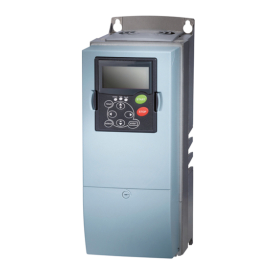
Quick Start Guide
Cutler-Hammer SVX9000 Drives from Eaton Corporation
CONTENT
STEP 1 — Keypad Operation Overview
STEP 2 — Standard Wiring Diagrams and Connections
STEP 3 — Start-Up Wizard
STEP 4 — Operating and Programming Menu
Navigation
STEP 5 — Faults and Warning Indication
STEP 6 — Monitoring Menu
MN04003009E
December 2003
Advertisement

Related Manuals for Eaton SVX900


Summary of Contents for Eaton SVX900
- Page 1 Quick Start Guide Cutler-Hammer SVX9000 Drives from Eaton Corporation CONTENT STEP 1 — Keypad Operation Overview STEP 2 — Standard Wiring Diagrams and Connections STEP 3 — Start-Up Wizard STEP 4 — Operating and Programming Menu Navigation STEP 5 — Faults and Warning Indication STEP 6 —...
-
Page 2: Keypad Operation Overview
STEP 1 Keypad Operation Overview Keypad and Display LCD Status Indicators Indicator Description Indicates that the SVX9000 is running and controlling the load. Blinks when a stop command has been given but the SVX9000 is still ramping down. Counterclockwise Operation The output phase rotation is BAC, corresponding to counterclockwise rotation of most motors. -
Page 3: Menu Navigation
STEP 1 (Continued) Navigation Buttons Button Description Start This button operates as the START button for normal operation when the “Keypad” is selected as the active control. Enter This button is used in the parameter edit mode to save the parameter setting and move to the next parameter …... - Page 4 STEP 1 (Continued) When in edit mode, the parameter value can be changed by pressing ● the up or down arrow keys. When in edit mode, pressing the right arrow a second time will allow ● you to edit the parameter value digit by digit. To confirm the parameter change you must press the ENTER button.
- Page 5 STEP 2 (Continued) Power Board 230V 20 – 30 hp 480V 40 – 250 hp Control Board L2 L3 (Optional) External External RFI-Filter Filter (Optional) (Optional) L2 L3 SVX9000 Power and Motor Wiring for Large Horsepower Drives (20 – 250 hp) MN04003009E December 2003...
- Page 6 STEP 2 (Continued) Basic Application Default I/O Configuration Terminal Signal Description Reference potentiometer 1 – 10 k NXOPTA9 +10V Reference output Voltage for potentiometer, etc. AI1+ Analog input, Voltage input frequency voltage range reference 0 – 10V DC AI1- I/O Ground Ground for reference and controls Remote reference...
-
Page 7: Startup Wizard
STEP 3 Start-Up Wizard If the wizard is not enabled at power-up, press the RESET button for 10 secs. to enable it. Startup Wizard Language Application “Press Enter” “English” “Basic” Setup Starts Min. Freq Max. Freq “Press Enter” “0.00” Hz “60.00”... - Page 8 STEP 4 Operating & Programming Menu Navigation Operate Menu Programming Output Freq Freq Reference Parameters “29.6” Hz “29.6” Hz Motor Speed Motor Current Keypad Control “885” rpm “0.09” A Motor Torque Motor Power Active Faults “2.6” % “0.5” % Motor Voltage DC –...
- Page 9 STEP 4 (Continued) Operate Menu — M8 The Operate Menu provides a easy to use method of viewing key numerical Monitoring Menu items. Some applications also support the setting of reference values in this menu. The items displayed vary by application. The table below is an example for the Standard application.
- Page 10 STEP 4 (Continued) Parameters — M1 Basic Parameters — M1 Code Parameter Min. Max. Unit Default Cust ID Note P1.1 Min frequency 0.00 P1.2 0.00 P1.2 Max frequency P1.1 320.00 Hz 60.00 102 NOTE: If f > motor synchronous speed, check suitability for motor and drive system P1.3...
- Page 11 STEP 4 (Continued) Input Signals — M1 ➔ G1.2 Code Parameter Min. Max. Unit Default Cust ID Note P1.2.1 Start/Stop logic 0 DIN1 DIN2 Start fwd Start rev Start/Stop Rev/Fwd Start/Stop enable Start pulse Stop pulse Start / Rev / Stop Start / Stop...
- Page 12 STEP 4 (Continued) Output Signals — M1 ➔ G1.3, continued Code Parameter Min. Max. Unit Default Cust ID Note P1.3.7 Digital output 1 312 0 = Not used function 1 = Ready 2 = Run 3 = Fault 4 = Fault inverted 5 = FC overheat warning 6 = Ext.
- Page 13 STEP 4 (Continued) Drive Control Parameters — M1 ➔ G1.4, continued Code Parameter Min. Max. Unit Default Cust ID Note P1.4.9 DC braking 0.00 600.00 s 0.00 0.00 = DC brake is off at time stop at stop P1.4.10 Frequency to 0.10 10.00 1.50...
- Page 14 STEP 4 (Continued) Protections — M1 ➔ G1.7 Code Parameter Min. Max. Unit Default Cust ID Note P1.7.1 Response to 700 0 = No response 4 mA reference 1 = Warning fault 2 = Warning+Previous Freq. 3 = Wrng+Preset Freq P1.7.2 4 = Fault, stop per P1.4.7...
- Page 15 STEP 4 (Continued) Keypad Control — M2 This menu provides the parameters for the setting of the keypad frequency reference, the selection of motor direction when in keypad operation, and when the STOP button is active. Table 1-1: Keypad Control Parameters — M2 Code Parameter Min.
- Page 16 Press the ENTER key to accept the change. Eaton Electrical 1000 Cherrington Parkway Moon Township, PA 15108-4312 tel: 1-800-525-2000 www.eatonelectrical.com © 2003 Eaton Corporation All Rights Reserved Publication No. MN0400309E/CPG December 2003 Printed in USA...
Need help?
Do you have a question about the SVX900 and is the answer not in the manual?
Questions and answers