Page 1
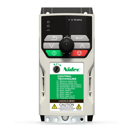
Quick Start Guide Unidrive M100-101 Frame sizes 1 to 4 Value drive with quality and performance for open loop applications Part Number: 0478-0035-08 Issue: 8...
Page 2
European Chemicals Agency (ECHA) to be a Substance of Very High Concern (SVHC) and is therefore listed by them as a candidate for compulsory authorisation. Further information on our compliance with REACH can be found at: http://www.drive-setup.com/reach Registered Office Nidec Control Techniques Ltd The Gro Newtown Powys SY16 3BE Registered in England and Wales.
Keypad and display ...................19 Saving parameters ....................20 Restoring parameter defaults .................20 Basic parameters (Menu 0) ...............21 Menu 0: Basic parameters ..................21 Unidrive M100/101 parameter descriptions ............26 Running the motor ..................41 Diagnostics ....................43 Alarm indications ....................46 NV Media Card Operation .................47 UL listing information ................48...
Page 5
EN 61000-3-2:2014 Applicable where input current < 16 A. No limits apply for professional equipment where input power 1 kW. These products comply with the Restriction of Hazardous Substances Directive (2011/65/EU), the Low Voltage Directive (2014/35/EU) and the Electromagnetic Compatibility Directive (2014/30/EU). Unidrive M100-101 Quick Start Guide Issue Number: 8...
Page 6
EMC. Refer to the Product Documentation. An EMC data sheet is available giving detailed information. The assembler is responsible for ensuring that the end product or system complies with all the relevant laws in the country where it is to be used. Unidrive M100-101 Quick Start Guide Issue Number: 8...
* A minimum clearance of 50 mm (1.97 in) above and below Frame 01 to 04 products is NOTE permissible in applications where either the ambient operating temperature is 35 °C (95 °F) or less or the average output current is derated by 20 %. Unidrive M100-101 Quick Start Guide Issue Number: 8...
Page 9
Drive size Tightening torque 1 to 3 1.3 N m (1 lb ft) to 1.6 N m (1.2 lb ft) 2.5 N m (1.8 lb ft) to 2.8 N m (2.1 lb ft) Unidrive M100-101 Quick Start Guide Issue Number: 8...
Page 10
7. Internal EMC filter screw 8. DC bus + 9. DC bus - 10. Motor connections 11. AC supply connections 12. Ground connections Before removing the screw, refer to section 4.5 EMC on page 17. Unidrive M100-101 Quick Start Guide Issue Number: 8...
The drive is provided with two ground connections to facilitate this. Both ground connections are necessary to meet EN 61800- WARNING 5-1: 2007. Unidrive M100-101 Quick Start Guide Issue Number: 8...
Action will only occur if the drive is inactive and no User Actions are running. Otherwise, the parameter will return to its pre altered value on exit from edit mode. All parameters are saved if this parameter changes. Unidrive M100-101 Quick Start Guide Issue Number: 8...
Page 15
Reference selected + 24 V output Analog reference 1* Preset speed 2* Reference select Preset speed 3* Preset speed 4* Drive enable Run forward Reference select * Refer to the Control User Guide. Unidrive M100-101 Quick Start Guide Issue Number: 8...
Page 16
The keypad reference can now be set to a negative frequency to run the motor in the reverse direction. + 24 V output Digital output (zero frequency) Drive enable Run forward Run reverse Unidrive M100-101 Quick Start Guide Issue Number: 8...
It is recommended that the filter be used in all applications unless the instructions given above require it to be removed, or where the ground leakage current is unacceptable. Unidrive M100-101 Quick Start Guide Issue Number: 8...
Page 18
A shielded control cable, with shield clamped to the grounded metal panel Full instructions are given in the Power Installation Guide. A full range of external EMC filters are also available for use with Unidrive M100 / 101, shown in the Power Installation Guide.
Figure 5-1 Unidrive M100 keypad detail Figure 5-2 Unidrive M101 keypad detail V A Hz rpm % V A Hz rpm % (1) The Enter button is used to enter parameter view or edit mode, or to accept a parameter edit.
2. Select 'Def.50’ or 'Def.60' in Pr 00 or Pr mm.000 (alternatively, enter 1233 (50 Hz settings) or 1244 (60 Hz settings) in Pr 00 or Pr mm.000). Press the red reset button Unidrive M100-101 Quick Start Guide Issue Number: 8...
NonE (0), rEAd (1), Prog (2), Auto (3), Parameter Cloning NonE (0) boot (4) CoASt (0), rP (1), rP.dc I (2), dc I (3), Stop Mode rP (1) td.dc I (4),diS (5) Unidrive M100-101 Quick Start Guide Issue Number: 8...
Page 22
Parameter Reference Guide for further details. Read / Read Number Binary Text string Filtered Write only parameter parameter parameter Protected Rating Power-down default User save DE Destination copied parameter dependent save value Unidrive M100-101 Quick Start Guide Issue Number: 8...
Page 24
Reference Selected Menu 0 only Input Read-write (RW) Read-write (RW) 00.XXX terminals parameter parameter Read-only (RO) Read-only (RO) Output 00.XXX parameter parameter terminals The parameters are all shown in their default settings Unidrive M100-101 Quick Start Guide Issue Number: 8...
Page 25
Rate 1 Deceleration Drive Rate 1 Ramp Mode Select Frequency Voltage Boost Motor Output Frequency Power stage Output Voltage Maximum Switching Frequency Motor Rpm Current Torque Magnitude Producing Current Magnetising Current Resistor optional Unidrive M100-101 Quick Start Guide Issue Number: 8...
0.0 to 32000.0 s/100 Hz 10.0 s/100 Hz Set Pr 04 at the required rate of deceleration. Note that larger values produce lower deceleration. The rate applies in both directions of rotation. Unidrive M100-101 Quick Start Guide Issue Number: 8...
Page 27
Def.60: 1800.0 rpm Set to the rated speed of the motor (taken from the motor name plate). The motor rated speed is used to calculate the correct slip speed for the motor. Unidrive M100-101 Quick Start Guide Issue Number: 8...
Page 28
Access to all menus. The keypad remains in status mode and no parameters can be viewed or StAtUS edited. The keypad remains in status mode and no parameters can be viewed or no.Acc edited. Unidrive M100-101 Quick Start Guide Issue Number: 8...
Page 29
4-20.S (-6), 20-4.S (-5), 4-20.L (-4), 20-4.L (-3), 4-20.H (-2), 20-4.H (-1), Volt (6) 0-20 (0), 20-0 (1), 4-20.tr (2), 20-4.tr (3), 4-20 (4), 20-4 (5), Volt (6) Defines the mode of analog input 1. Unidrive M100-101 Quick Start Guide Issue Number: 8...
Page 30
This parameter and Status Mode Parameter 1 (Pr 23) define which parameters are displayed in Status mode. The values can be alternated by pressing the Escape button, if the drive is running. Unidrive M100-101 Quick Start Guide Issue Number: 8...
Page 31
Defines which value of keypad control mode reference is displayed at power-up. Value Text Description rESEt Keypad reference is zero LASt Keypad reference is the last used value PrESEt Keypad reference is copied from Preset Reference 1 (Pr 18) Unidrive M100-101 Quick Start Guide Issue Number: 8...
Page 32
Read parameter set from the NV Media Card Programming a parameter set to the NV Prog Media Card Auto Auto save boot Boot mode For further information, please refer to Chapter 9 NV Media Card Operation on page 47. Unidrive M100-101 Quick Start Guide Issue Number: 8...
Page 33
If a stator resistance is not measured, the drive may trip on OV or OI.AC while trying to catch a spinning motor. Pr 33 Text Function Disabled Enable Detect all frequencies Fr.Only Detect positive frequencies only Rv.Only Detect negative frequencies only Unidrive M100-101 Quick Start Guide Issue Number: 8...
Page 34
Frequency lower limit Drive running at zero frequency Drive ready Drive OK Brake release Torque limiting (Valid while the torque is limited by torque limiting value 1/2) Forward or reverse Motor 1 or 2 Unidrive M100-101 Quick Start Guide Issue Number: 8...
Page 35
The enable signal must be removed before the drive can be made to run at the required reference.The drive can be stopped at any time by removing the run WARNING signal or removing the drive enable. Unidrive M100-101 Quick Start Guide Issue Number: 8...
Page 36
Not selecting another mode could result in poor motor performance or OI.AC, It.AC or OV trips. Low Frequency Voltage Boost 0.0 to 25.0 % 3.0 % Determines the boost level when Pr 41 is set to Fd, SrE or Fd.tap modes. Unidrive M100-101 Quick Start Guide Issue Number: 8...
Page 37
Displays the maximum heavy duty current rating of the drive. Software Version 0 to 99.99.99 Displays the software version in the drive. User Drive Mode OPEn.LP (1) OPEn.LP (1) The user drive mode is open-loop only. Unidrive M100-101 Quick Start Guide Issue Number: 8...
Page 38
The Output Frequency is the sum of the Post Ramp Reference and the motor slip compensation frequency. Output Voltage 0 to 325 V or 0 to 650 V The Output Voltage is the r.m.s line to line voltage at the a.c. terminals of the drive. Unidrive M100-101 Quick Start Guide Issue Number: 8...
Page 39
Digital I/O Read Word reflects the state of digital inputs/outputs 1 to 4 and the relay. Reference On Off (0) or On (1) Reference On, which is controlled by the drive sequencer, indicates that the reference from the reference system is active. Unidrive M100-101 Quick Start Guide Issue Number: 8...
Page 40
Jog Select, which is controlled by the drive sequencer, is used to select the Jog Reference (Pr 15). Analog Input 1 ±100.00 % This parameter displays the level of the analog signal present at analog input 1 (terminal 2). Unidrive M100-101 Quick Start Guide Issue Number: 8...
The drive will display ’rdy’. • Give a Run command (apply +24 V to terminal 12 - Run forward or terminal 13 - Run reverse on Unidrive M100; L press keypad Start button on M101). The display will flash ’tuning’ while the drive is performing the autotune.
Page 42
Ready to run The drive is now ready to run the motor. Close the Run Forward or Run Reverse terminals on Unidrive M100; press keypad Start button on M101. Changing the selected Analog frequency reference (Speed Ref Increasing and Potentiometer on M101) will increase and decrease the speed of decreasing speed the motor.
The EEF trip indicates that default parameters have been loaded. Default parameters have been The exact cause/reason of the trip can be identified from the sub- loaded trip number (see Control User Guide). Unidrive M100-101 Quick Start Guide Issue Number: 8...
Page 44
• Check braking resistor insulation OI.SC Output phase short-circuit Over-current detected on drive output when enabled. Out.P Output phase loss detected Phase loss has been detected at the drive output. Unidrive M100-101 Quick Start Guide Issue Number: 8...
Page 45
User Over Current Trip Level. Refer to the Control User Guide. The U.S trip indicates that an error has been detected in the user User Save error / not completed save parameters saved in non-volatile memory. Unidrive M100-101 Quick Start Guide Issue Number: 8...
Low voltage mode. See Low AC Alarm in Control User Guide. I.AC.Lt Current limit active. See Current Limit Active in Control User Guide. 24.LoSt 24V backup not present. See 24V Alarm Loss Enable in the Control User Guide. Unidrive M100-101 Quick Start Guide Issue Number: 8...
If this occurs then either the transfer should be reattempted or in the case of a card to drive transfer, default parameters should be loaded. NOTE The drive supports SD cards formatted with the FAT32 file system only. Unidrive M100-101 Quick Start Guide Issue Number: 8...
Where possible, UL Listed closed-loop connectors sized according to the field wiring shall be used for all field power wiring connections. GROUND CONNECTION INSTRUCTIONS UL Listed closed-loop connectors sized according to the field wiring shall be used for grounding connections. Unidrive M100-101 Quick Start Guide Issue Number: 8...
10.8 External Class 2 supply The external power supply used to power the 24 V control circuit shall be marked: “UL Class 2”. The power supply voltage shall not exceed 24 Vdc. Unidrive M100-101 Quick Start Guide Issue Number: 8...
Page 50
Quick start setup using default parameter settings Digital I/O Analog I/O 24 V user Analog input 1 Digital I/O1 Frequency Zero frequency reference 10 V user Digital Input 2 Drive enable Digital input 3 Run forward Digital input 4 DC bus/Brake Run reverse Relay Drive ok...
Need help?
Do you have a question about the Unidrive M100 and is the answer not in the manual?
Questions and answers