Sign In
Upload
Manuals
Brands
Nidec Manuals
Controller
HVAC Drive H300
Nidec HVAC Drive H300 Variable Speed Manuals
Manuals and User Guides for Nidec HVAC Drive H300 Variable Speed. We have
5
Nidec HVAC Drive H300 Variable Speed manuals available for free PDF download: User Manual, Step-By-Step Manual, Quick Startup And Operation Manual, Installation Sheet
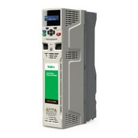
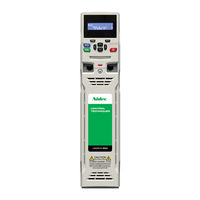
Nidec HVAC Drive H300 User Manual (323 pages)
HVAC DRIVE Model sizes 3-11 Universal Variable Speed AC drive for induction and permanent magnet motors
Brand:
Nidec
| Category:
Controller
| Size: 36.57 MB
Table of Contents
How to Use this Guide
3
12 Technical Data
3
Table of Contents
4
1 Safety Information
9
Electrical Hazards
9
Mechanical Hazards
9
Hazardous Environments
9
Warnings, Cautions and Notes
9
Important Safety Information. Hazards. Competence of Designers and Installers
9
Responsibility
9
Compliance with Regulations
9
Stored Electrical Charge
9
Access to Equipment
9
Mechanical Brake Control
10
Adjusting Parameters
10
Electromagnetic Compatibility (EMC)
10
2 Product Information
11
Drive Firmware Version
11
Features
11
AC Drive for Fans, Pumps and Compressors
11
Model Number
12
Fire Mode - Important Warning
12
Ratings
13
Operating Modes
16
Typical Short Term Overload Limits
16
Open Loop Mode
16
RFC-A Sensorless/Rfc- S Sensorless
16
Drive Features
17
Features of the Drive View (Size 11E)
18
Nameplate Description
19
Options
20
Option Module Identification
21
Keypad Identification
21
Additional Options
21
Items Supplied with the Drive
22
3 Mechanical Installation
24
Planning the Installation
24
Cooling
24
Fire Protection
24
Safety Information
24
Terminal Cover Removal
25
Electromagnetic Compatibility
25
Removing the Terminal Covers
26
Location and Identification of Terminal Covers (Size 11)
27
Removing the Size 3 Terminal Covers
28
Removing the Size 4 Terminal Covers
28
Removing the Size 5 Terminal Covers
29
Removing the Size 6 Terminal Covers
29
Removing the Size 7 to 11 Terminal Covers (Size 7 Shown)
30
Removing the Finger-Guard and DC Terminal Cover Break-Outs
30
Grommet Kits
30
Removing the Size 3 and 4 DC Terminal Cover Break-Outs
31
Installing / Removing Option Modules and Keypads
32
Removal of a Standard Option Module
33
Installation and Removal of the KI-Keypad
33
Dimensions and Mounting Methods
34
Surface Mounting
34
Surface Mounting the Size 4 Drive
35
Surface Mounting the Size 5 Drive
35
Surface Mounting the Size 6 Drive
36
Surface Mounting the Size 7 Drive
36
Surface Mounting the Size 8 Drive
37
Surface Mounting the Size 9A
38
Surface Mounting the Size 9E and 10E
39
Surface Mounting the Size 11E
40
Through-Panel Mounting the Size 3 Drive
41
Through Panel Mounting the Size 4 Drive
42
Through Panel Mounting the Size 5 Drive
42
Through Panel Mounting the Size 6 Drive
43
Through Panel Mounting the Size 7 Drive
43
Through Panel Mounting the Size 8 Drive
44
Through Panel Mount Detail for Size 9A
44
Through-Panel Mounting the Size 9E and 10E
45
Through Panel Mounting the Size 11E
46
Mounting Brackets
47
Enclosure for Standard Drives
48
Recommended Spacing between the Drives
48
Mounting Brackets (Size 11)
48
Enclosure Layout
49
Spacing Required between Drive / Enclosure and Drive / EMC Filter
49
Enclosure Layout (Size 9 to 11)
50
Enclosure Sizing
51
Calculating the Size of a Sealed Enclosure
51
Calculating the Air-Flow in a Ventilated Enclosure
51
Enclosure Design and Drive Ambient Temperature
52
Heatsink Fan Operation
52
Enclosing Standard Drive for High Environmental Protection
52
Installing the Gasket
53
Through Panel Mounting
53
Installation of High IP Insert for Size 3
53
Installation of High IP Insert for Size 4
54
Installation of High IP Insert for Size 5
54
Environment Considerations
54
Example of IP55 (NEMA 12) Size 9 to 11 Through-Panel Layout
55
View Showing Sealing Clamps Provided in through Hole Mounting Kit
56
Power Losses from the Front of the Drive When Through-Panel Mounted
56
External EMC Filter Data
57
Footprint Mounting the EMC Filter
58
Bookcase Mounting the EMC Filter
58
Size 7 to 11 Mounting of the EMC Filter
58
External EMC Filter (Size 3 to 6)
58
External EMC Filter (Size 7 to 8)
59
Size 4 External EMC Filter Dimensions
59
Size 6 External EMC Filter Dimensions
59
Size 7 External EMC Filter Dimensions
59
External EMC Filter (Size 9A)
60
Size 9A External EMC Filter Dimensions
60
External EMC Filter (Size 9E and 10)
61
Size 9E and 10E External EMC Filter Dimensions
61
External EMC Filter (Size 11)
62
Size 11 External EMC Filter Dimensions
62
Line Reactor Mounting Dimensions for Size 9E,10E and 11E
63
Input Line Reactor (INLX0X) for Size 9 and 10
63
Input Line Reactor (INLX0X) for Size 11
63
Electrical Terminals
64
Location of the Power and Ground Terminals (Size 3 to 8)
64
Location of the Power and Ground Terminals (Size 9A/9E, 10E and 11E)
65
Terminal Sizes and Torque Settings
66
Drive Power Terminal Data
66
Plug-In Terminal Block Maximum Cable Sizes
66
External EMC Filter Terminal Data
66
Routine Maintenance
67
Real Time Clock Battery Replacement
67
Size 3 to 5 Heatsink Fan Removal Procedure
68
Size 3 to 5 Heatsink Fan Part Numbers
68
Size 6 Heatsink Fan Removal Procedure
69
Size 7 Heatsink Fan Replacement
70
Size 8 Heatsink Fan Replacement
71
Size 9 to 11 Heatsink Fan Replacement
72
Size 6 Auxiliary (Capacitor Bank) Fan Replacement
73
Size 7 to 11 Auxiliary (Capacitor Bank) Fan Replacement
74
Size 7 to 11 Auxiliary (Capactitor Bank) Fan Part Numbers
74
4 Electrical Installation
75
Power Connections
75
AC and DC Connections
75
Size 4 Power Connections
76
Size 5 Power Connections
76
Size 6 Power Connections
77
Size 7 and 8 Power Connections
77
Size 9A Power and Ground Connections
78
Size 9E and 10E Power Connections
78
Ground Connections
79
AC Supply Requirements
80
Protective Ground Cable Ratings
80
Supply Types
81
Supplies Requiring Line Reactors
81
Reactor Current Ratings
81
Drive Model and Input Line Reactor
82
Drive Model and Line Reactor Part Number
82
Input Line Reactor Ratings (2%)
83
Supplying the Drive with DC
84
Input Inductor Calculation
84
Input Line Reactor Dimensions
84
DC Bus Paralleling
85
24 VDC Supply
86
The Working Range of the 24 V Power Supply
86
Location of the 24 VDC Power Supply Connection on Size 6
86
Low Voltage Operation
87
Location of the 24 VDC Power Supply Connection on Size 8 to 11
87
Heatsink Fan Supply
88
Maximum Continuous Input Current
88
Location of the Heatsink Fan Supply Connector on Size 9 to 11
88
Ratings
88
AC Input Current and Fuse Ratings (200 V)
89
AC Input Current and Fuse Ratings (400 V)
89
AC Input Current and Fuse Ratings (575 V)
90
AC Input Current and Fuse Ratings (690 V)
90
Cable Ratings (200 V)
91
Cable Ratings (400 V)
91
Cable Ratings (575 V)
92
Cable Ratings (690 V)
92
Output Circuit and Motor Protection
93
Cable Types and Lengths
93
Maximum Motor Cable Lengths (200 V Drives)
93
Maximum Motor Cable Lengths (400 V Drives)
93
Motor Winding Voltage
94
Multiple Motors
94
High-Capacitance / Reduced Diameter Cables
94
Cable Construction Influencing the Capacitance
94
Ground Leakage
95
Motor Operation
95
Use of Residual Current Device (RCD)
95
Output Contactor
95
EMC (Electromagnetic Compatibility)
96
Drive and EMC Filter Cross Reference
96
Grounding Hardware
97
Installation of Grounding Clamp
97
Internal EMC Filter
98
Installation of Grounding Bracket
98
Line to Ground Varistors
99
General Requirements for EMC
100
Ground (Earth) Connections
100
Cable Layout
101
Drive Cable Clearances
101
Compliance with en 61800-3:2004 (Standard for Power Drive Systems)
101
Compliance with Generic Emission Standards
101
Supply and Ground Cable Clearance (Size 7 Onwards)
102
Grounding the Drive, Motor Cable Shield and Filter
102
Sensitive Signal Circuit Clearance
102
Variations in the EMC Wiring
103
Interruptions to the Motor Cable
103
Using a Motor Isolator / Disconnect-Switch
103
Grounding the Motor Cable Shield
103
Communications Connections
104
Isolation of the EIA-485 Serial Communications Port
104
Surge Immunity of Control Circuits
104
Control Connections
105
Control Terminal Specification
106
Building Automation Network Connections
108
Safe Torque off (STO)
109
Understanding the Display
111
Keypad Operation
111
Control Buttons
111
Hand / off / Auto
111
5 Getting Started
111
Display Modes
112
Power-Up Modes if Pr 1.052 = 3
112
Quick Access Mode
113
Keypad Shortcuts
113
Mode Examples
113
Menu Structure
114
Menu 0
114
Advanced Menus
115
KI-HOA Keypad RTC
115
Display Messages
115
Keypad Set-Up Parameters
115
Changing the Operating Mode
116
Saving Parameters
116
Alarm Indications
116
Restoring Parameter Defaults
117
Parameter Access Level and Security
117
User Security Level / Access Level
117
User Security Code
117
Displaying Parameters with Non-Default Values Only
118
Displaying Destination Parameters Only
118
Communications
118
KI-485 Adaptor Installation
118
Serial Communications Set-Up Parameters
119
6 Basic Parameters
120
Menu 0: Basic Parameters
120
Menu 0 Logic Diagram
124
Parameter Descriptions
126
Pr MM.000
126
Commonly Used Functions in XX.000
126
Functions in Pr MM.000
127
Full Descriptions
128
Parameter X.00
128
Monitoring
128
Status Information
129
Speed Limits
129
Ramps
129
Voltage Boost, (Open-Loop), Speed-Loop PID Gains (RFC-A/RFC-S)
129
Motor Parameters
130
Fixed and Variable V/F Characteristics
130
Open-Loop
130
Rfc-S
130
RFC-A Mode
131
Rated Current
131
Rated Frequency
131
Maximum Switching Frequency
131
Analog Input 1 Mode
132
Analog Input 1 Destination
132
Analog Input 2 Mode
133
Analog Input 2 Destination
133
Analog Input 2 Thermistor Type
133
User Security Status
133
Parameter Cloning
134
Date
134
Time
134
Day of Week
134
Additional Parameters for RFC-S Sensorless Control
135
Non-Salient
135
Current
135
Current no Test
135
Injection Mode
136
Non-Salient Mode
136
Low Speed Sensorless Mode Current Limit
136
Phase Offset at Iq Test Current
136
Number of Auto Reset Attempts
137
Auto Reset Delay
137
Trip 0 to Trip 9
137
7 Running the Motor
138
Quick Start Connections
138
Changing the Operating Mode
138
Minimum Connections to Get the Motor Running in any Operating Mode
139
Quick Start Commissioning / Start-Up
143
RFC - a Sensorless
144
Induction Motor Without Position Feedback
144
RFC-S Sensorless
145
Permanent Magnet Motor Without Position Feedback
145
Power-Up the Drive
146
Quick Start Commissioning / Start-Up Using HVAC Drive Connect (V02.00.05 Onwards)
146
Use of Motor Database for Use in RFC-S Sensorless Mode
148
8 Optimization
151
Motor Map Parameters
151
Open Loop Motor Control
151
Rated Power Factor
151
Autotune
152
Open Loop Control Mode
152
Enable Slip Compensation
153
RFC-A Sensorless Mode
154
Current Loop Gains
155
Speed Loop Gains
156
Speed Controller Proportional Gain
156
Speed Controller Integral Gain
156
Differential Gain
156
RFC-S Sensorless Mode
157
Number of Motor Poles
157
Sensorless Mode Filter
157
RFC Low Speed Mode/Low Speed Sensorless Mode Current
158
Current Reference Filter 1 Time Constant
158
Pr 04.013/Pr 04.014 Current Loop Gains
158
Motor Thermal Protection
160
Available Switching Frequencies
161
Sample Rates for Various Control Tasks at each Switching Frequency
161
High Speed Operation
162
Field Weakening (Constant Power) Operation
162
Permanent Magnet Motor High Speed Operation
162
Maximum Speed/Frequency / Quasi-Square Wave (Open-Loop Only)
162
Fire Mode
163
Advanced Process PID
163
Fire Mode Reference
163
Fire Mode Activation
163
HVAC Drive H300 Issue Number
163
PID Main Reference Source Parameter
164
PID 1 Reference Slew-Rate Limit
164
PID 1 Optional Enable Source Parameter 1
164
PID 1 Proportional Gain
164
PID 1/2 Output Scaling
165
PID 1/2 Integrator Hold
165
PID 1/2 Symmetrical Limit Enable
165
PID 1 Pre-Sleep Boost Level Enable
165
Analog Reference Profile
166
PID 1 Feedback Output Scaling
166
Combined PID Square Root Enable
166
PID Mode Selector
166
9 NV Media Card Operation
167
NV Media Card Support
167
Introduction
167
Transferring Data
168
Writing to the NV Media Card
168
Reading from the NV Media Card
168
Data Block Header Information
169
Booting up from the NV Media Card on Every Power up
169
Comparing the Drive Full Parameter Set with the NV Media Card Values
169
Erasing Data from the NV Media Card Values
169
NV Media Card Parameters
170
NV Media Card File Previously Loaded
170
NV Media Card File Number
170
NV Media Card Type
170
NV Media Card Trips
171
NV Media Card Warning Suppression Flag
171
Building Automation Network Communications Set up Parameters
172
Serial Address
172
Introduction
172
Serial Mode
173
Serial Baud Rate
173
Building Automation Network (BAN) Protocol Selection
174
Bacnet MS/TP Maximum Master MAC Address
174
Communications Lost Detection Time-Out Period
174
Communications Lost Action
174
CT Modbus RTU Specification (EIA-485)
175
Slave Address
175
MODBUS Registers
176
Data Consistency
176
Data Encoding
176
Function Codes
176
FC03 Read Multiple
177
FC06 Write Single Register
177
FC16 Write Multiple
177
Slave Response
177
FC23 Read/Write Multiple
178
Extended Data Types
179
Exceptions
180
Exception Message Format
180
Exception Codes
180
Bacnet Specification
181
Device Compatibility Parameters
181
Analog Input Objects
182
Analog Output Objects
182
Device Object Properties
182
Analog Value Objects
183
Binary Input Objects
184
Binary Output Objects
184
Binary Value Objects
184
Metesys N2 Specification
185
Region Types
185
Analog Inputs
186
Object Configuration
187
Object Status
187
Supported Attributes for Analog Inputs
187
COS Status Bits
187
Binary Inputs
188
Binary Input Points
188
Binary Input Point Attributes
188
Binary Input-Object Configuration Byte
188
Analog Outputs
189
Analog Output Point Attributes
189
Analog Output-Object Configuration Byte
189
Analog Output-Object Status Byte
189
Binary Outputs
190
Binary Output Point Attributes
190
Binary Output Configuration Byte
190
Binary Output Status Byte
190
Internal Float Values (Used to Access Specified Drive Parameters)
191
Internal Float Value Points
191
Internal Float Value Status Byte
191
Attributes Supported for Internal Float Values
191
List of Metasys Commands Supported
192
List of Metasys Commands NOT Supported
192
Change of State Support
192
Selecting Points for COS Polling
192
How a Change-Of-Stage Is Evaluated
193
Alarms for Analog Inputs
193
Analog Input Object Configuration Byte/Status Byte
193
COS Status Bit State Table
193
Alarms for Binary Inputs
194
Alarm/Warning Bits for Various Measurement Points
194
Binary Input Object Configuration Byte
194
Binary Input Object Status Byte
194
11 Advanced Parameters
195
Key to Parameter Table Coding
195
Feature Look-Up Table
196
Parameter Ranges and Variable Minimum/Maximums
198
Vm_Ac_Voltage
198
Vm_Ac_Voltage_Set
198
Vm_Accel_Rate
198
Vm_Dc_Voltage
199
Vm_Drive_Current
199
Vm_Drive_Current_Unipolar
199
Vm_High_Dc_Voltage / Vm_Low_Under_Volts
199
Vm_Min_Switching_Frequency
200
Vm_Motor1_Current_Limit / Vm_Motor2_Current_Limit
200
Vm_Negative_Ref_Clamp1 / Vm_Negative_Ref_Clamp2
200
Vm_Positive_Ref_Clamp1 / Vm_Positive_Ref_Clamp2
201
Vm_Power
201
Vm_Rated_Current
201
Vm_Speed
202
Vm_Speed_Freq_Keypad_Ref
202
Vm_Speed_Freq_Ref
203
Vm_Speed_Freq_Ref_Unipolar
203
Vm_Speed_Freq_User_Refs
203
Vm_Std_Under_Volts
203
Vm_Supply_Loss_Level
204
Vm_Switching_Frequency
204
Vm_Torque_Current
204
Vm_Torque_Current_Unipolar
204
Vm_User_Current
205
Vm_User_Current_High_Res
205
Voltage Ratings Dependant Values
205
Menu 1: Frequency / Speed Reference
206
Menu 2: Ramps
210
Menu 3: Speed Feedback and Speed Control
213
Menu 4: Torque and Current Control
217
Menu 4 Open Loop Logic Diagram
217
Menu 4 RFC-A Logic Diagram
218
Menu 4 RFC-S Logic Diagram
219
Menu 5: Motor Control
221
Menu 5 Open-Loop Logic Diagram
221
Menu 5 RFC-A, RFC-S Logic Diagram
222
Menu 6: Sequencer and Clock
226
Menu 6 Logic Diagram
226
Menu 7: Analog I/O
229
Menu 7 Logic Diagram
229
Menu 8: Digital I/O
232
Menu 8 Logic Diagram
232
Menu 9: Programmable Logic, Motorized Pot, Binary Sum and Timers
236
Menu 9 Logic Diagram: Programmable Logic
236
Menu 9 Logic Diagram: Motorized Pot and Binary Sum
237
Menu 9 Logic Diagram: Timers
238
Menu 9 Logic Diagram: Scope Function
239
Menu 10: Status and Trips
242
Defaults for Pr 10.030, Pr 10.031 and Pr 10.061
243
Menu 11: General Drive Set-Up
244
Menu 12: Threshold Detectors and Variable Selectors
246
Menu 12 Logic Diagram
246
Menu 14: User PID Controller
250
Menu 14 Logic Diagram
250
Menus 15, 16 and 17: Option Module Set-Up
254
Location of Option Module Slots and Their Corresponding Menu Numbers
254
Parameters Common to All Categories
254
Menu 18: Application Menu 1
255
Menu 19: Application Menu 2
255
Menu 20: Application Menu 3
255
Menu 22: Additional Menu 0 Set-Up
256
Menu 29: Building Automation Network Setup
258
Drive Technical Data
259
Maximum Permissible Continuous Output Current @ 40 Degrees C Ambient
259
Power and Current Ratings
259
Maximum Permissible Continuous Output Current @ 50 Degrees C (122 F)
262
Losses @ 40 Degrees C (104 F) Ambient
264
Power Dissipation
264
Losses @ 40 Degrees C (104 F) Ambient with High IP Insert Installed
266
Losses @ 50 Degrees C (122 F) Ambient
267
IP / UL Rating
269
Line Reactors
269
Motor Requirements
269
Supply Requirements
269
Accuracy and Resolution
270
Corrosive Gasses
270
Start up Time
270
Vibration
270
Acoustic Noise
271
Overall Dimensions
271
Overall Drive Weights
271
AC Input Current and Fuse Ratings
272
Cable Ratings
274
Maximum Motor Cable Lengths
276
Torque Settings
278
Drive Control and Relay Terminal Data
278
Immunity Compliance
280
Emission Compliance
280
Optional External EMC Filters
283
EMC Filter Cross Reference
283
EMC Filter Ratings
284
Overall EMC Filter Dimensions
284
EMC Filter Torque Settings
285
Diagnostics - Information Provided by Keypad Display
286
Status Modes (Keypad and LED Status)
286
Trip Indications
286
Identifying a Trip / Trip Source
287
Key to Sub-Trip Number
287
Sub-Trip Identification
287
Trips, Sub-Trip Numbers
288
An Input 1 Loss
288
Autotune 1
288
App Menu Changed
288
Autotune 2/3/7
289
Autotune Stopped
289
Brake R too Hot
289
Card Access
289
Card Boot
290
Card Busy
290
Card Compare
290
Card Data Exists/Card Drive Mode/Card Error/Card Full
290
Card no Data
291
Card Product
291
Card Rating
291
Card Read Only/Card Slot
291
Configuration
292
Control Word
292
Current Offset
292
Data Changing/Derivative ID
292
Derivative Image
293
Destination
293
Drive Size
293
EEPROM Fail
294
Encoder 9
294
External Trip
294
Hf01
294
Hf02 - Hf11
295
Hf12 - Hf19
296
Hf20
297
HF23 to HF25
297
I/O Overload
297
Inductance
297
Inter-Connect
298
Keypad Mode
298
Motor too Hot
298
Name Plate
299
Oht Brake
299
Oht Control
299
Oht DC Bus
300
Oht Inverter
300
Oht Power
301
OI Ac
301
OI Brake
302
OI DC
302
OI Snubber
302
Option Disable
302
Out Phase Loss
303
Over Speed
303
Over Volts
303
Phase Loss
304
Phasing Error
304
Power Comms
304
Power Data
305
Power down Save
305
Psu
305
Psu 24V
305
Rating Mismatch
306
Rectifier Set-Up
306
Reserved
306
Resistance/Slot App Menu
306
Slotx Different
307
Slotx Error
307
Slotx HF
307
Slotx Not Fitted/Slotx Watchdog
307
Soft Start
308
Stored HF
308
Sub-Array RAM
308
Temp Feedback/Th Brake Res
308
Th Short Circuit
309
Thermistor
309
Undefined
309
User 24V
309
User Program
310
User Prog Trip
310
User Save
311
User Trip
311
Watchdog
311
Serial Communications Look up Table
312
Trip Categories
313
Internal / Hardware Trips
314
Status Indications
314
Programming Error Indications
314
Displaying the Trip History
315
Behaviour of the Drive When Tripped
315
14 UL Listing Information
316
Enclosure Ratings
316
Mounting
316
Environment
316
UL File Reference
316
Option Modules, Kits and Accessories
316
Electrical Installation
316
Motor Overload Protection and Thermal Memory Retention
317
External Class 2 Supply
317
Requirement for Transient Surge Suppression
317
Group Installation and Modular Drive Systems
317
Electrical Supply
317
Alphabetical Index
318
Advertisement
Nidec HVAC Drive H300 Step-By-Step Manual (47 pages)
Brand:
Nidec
| Category:
DC Drives
| Size: 8.56 MB
Table of Contents
Table of Contents
2
Introduction
3
STEP 1: Check the Contents of the Box
5
STEP 2: Check Model and Voltage
5
STEP 3: Mount the Drive
6
STEP 4: Select Supply / Motor Cables and Fuses
7
STEP 5: Remove the Finger Guard Breakouts
11
STEP 6: Wire the Drive up
12
STEP 7: Use the Keypad
25
STEP 8: Run the Drive for the First Time in Hand Mode
26
STEP 9: Running the Drive in Auto Mode
37
Additional Information
38
UL Information
43
Nidec HVAC Drive H300 Step-By-Step Manual (42 pages)
Brand:
Nidec
| Category:
DC Drives
| Size: 5.78 MB
Table of Contents
Table of Contents
2
Introduction
3
Check the Contents of the Box
4
Check Model and Voltage
4
Mount the Drive
5
Select Supply / Motor Cables and Fuses
8
Wire the Drive up
10
Use the Keypad
20
Run the Drive for the First Time in Hand Mode
21
Running the Drive in Auto Mode
32
Additional Information
33
UL Information
37
Leroy Somer Permanent Magnet Motor Data
40
Advertisement
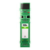
Nidec HVAC Drive H300 Quick Startup And Operation Manual (13 pages)
Brand:
Nidec
| Category:
Controller
| Size: 1.94 MB
Table of Contents
Control Wiring
4
Keypad and Display
5
Open Loop Startup
6
Alarm Indications
7
Basic Parameters (Menu 0)
8
NV Media Card Support
11
Nidec HVAC Drive H300 Installation Sheet (2 pages)
Brand:
Nidec
| Category:
DC Drives
| Size: 0.76 MB
Advertisement
Related Products
Nidec Digitax HD M75X Series
Nidec Digitax HD M75 Series
Nidec Digitax HD M750 Ethernet
Nidec Digitax HD M751 Base
Nidec Digitax HD M753 EtherCAT
Nidec Digitax HD M754
Nidec Control Techniques HVAC Drive H300 HMI Bypass
Nidec H300-03200066A
Nidec H300-03200080A
Nidec H300-03200110A
Nidec Categories
Measuring Instruments
DC Drives
Industrial Equipment
Controller
Test Equipment
More Nidec Manuals
Login
Sign In
OR
Sign in with Facebook
Sign in with Google
Upload manual
Upload from disk
Upload from URL