Table of Contents
Advertisement
Quick Links
Read this manual before working with the product. For personal and system safety and for optimum product
performance. Make sure you thoroughly understand the contents before installing, using or maintaining the
Manufactured by:
www.klay-
H/EN/2000-VALVE/02-2021/05
INSTRUCTION MANUAL
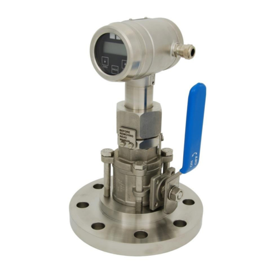
PRESSURE-AND LEVEL TRANSMITTER
SERIES 2000-VALVE-RANGE.
SERIES 2000-VALVE-RANGE
7991 CZ DWINGELOO
7990 AA DWINGELOO
The Netherlands
E-mail:
info@klay.nl
WARNING
Nijverheidsweg 5
P.O. Box 13
Tel: +31-521-591550
Fax: +31 -521-592046
instruments.com
KLAY INSTRUMENTS B.V.
Advertisement
Table of Contents

Subscribe to Our Youtube Channel
Related Manuals for KLAY-INSTRUMENTS 2000-VALVE-RANGE Series


Summary of Contents for KLAY-INSTRUMENTS 2000-VALVE-RANGE Series
- Page 1 INSTRUCTION MANUAL PRESSURE-AND LEVEL TRANSMITTER WARNING Read this manual before working with the product. For personal and system safety and for optimum product performance. Make sure you thoroughly understand the contents before installing, using or maintaining the SERIES 2000-VALVE-RANGE. SERIES 2000-VALVE-RANGE Manufactured by: 7991 CZ DWINGELOO Nijverheidsweg 5...
-
Page 2: Table Of Contents
Instruction Manual Series 2000-RANGE-VALVE Klay Instruments B.V. CONTENTS SECTION PAGE Introduction Description Series 2000-VALVE-RANGE Barometric reference Dimensional drawings ” Parts description 1 model ” Parts description 1,5 model Before Welding Welding & Installing transmitter Installing transmitter Mounting position Mounting position effect Calibration Wiring Remaining... -
Page 3: Introduction
Instruction Manual Series 2000-RANGE-VALVE Klay Instruments B.V. INTRODUCTION DESCRIPTION SERIES 2000-VALVE-RANGE The Series 2000-VALVE-RANGE is a unique combination of the series 2000 and ball Valve. The Series 2000-VALVE-RANGE is specially designed for the pulp- and paper industry or similar, where clogging is a problem. -
Page 4: Dimensional Drawings
Instruction Manual Series 2000-RANGE-VALVE Klay Instruments B.V. 2. DIMENSIONAL DRAWING 2.1 PARTS DESCRIPTION (1”) Cover AISI 304 Push buttons + display ( behind cover) Cover with venting AISI 304 Venting PG9 cable gland Electronics housing AISI 304 Hexagon nut, SW 41 AISI 304 Stop AISI 316... -
Page 5: Welding & Installing Transmitter
Instruction Manual Series 2000-RANGE-VALVE Klay Instruments B.V. WELDING AND INSTALLING TRANSMITTER For welding and installing the Series 2000-VALVE-RANGE the instructions on the next page must be followed exactly. This is extremely important to ensure a good working of the system. Warning: Warning: Improper installation may result in weld spud distortion... -
Page 6: Installing Transmitter
Instruction Manual Series 2000-RANGE-VALVE Klay Instruments B.V. WARNING: BEFORE OPENING THE VALVE, MAKE SURE THE TRANSMITTER IS LOCKED. BE SURE THE VALVE IS CLOSED WHEN HE TRANSMITTER IS RETRACTED FROM VALVE. THIS IS EXTREMELY IMPORTANT OTHERWISE THE TRANSMITTER WILL PUSH OUT OF THE PROCESS. INSTALLING TRANSMITTER SERIES 2000-VALVE-RANGE The position of the valve depends on the welding position of the weld-on nipple. -
Page 7: Remaining
Instruction Manual Series 2000-RANGE-VALVE Klay Instruments B.V. REMAINING DIGITAL LOCAL INDICATOR All transmitters from the Series 2000-VALVE-RANGE are standard equipped with a digital display. In the standard execution the covers are "closed". The three push buttons and the display are behind the cover (3). -
Page 8: Functions Of Push Buttons
Instruction Manual Series 2000-RANGE-VALVE Klay Instruments B.V. FUNCTIONS OF PUSH BUTTONS The Series 2000-VALVE-RANGE can be programmed easily by use of the 3 front panel pushbuttons (See picture right). The display can show engineering units of: O, inH O, bar and PSI. The functions of the three pushbuttons will be explained below. -
Page 9: Programming Points (P101-P114)
Instruction Manual Series 2000-RANGE-VALVE Klay Instruments B.V. Programming points: 6. PROGRAMMING POINTS (P101 – P116) P101 Zero adjustment (4 mA) P102 Span adjustment (20 mA) The following points can be adjusted by means of P103 Cancel mounting position effect the three push buttons. Adjustment pressure unit P104 For an explanation of these points see page 10 to... -
Page 10: Explanation Programming Points P101 To P116
Instruction Manual Series 2000-RANGE-VALVE Klay Instruments B.V. EXPLANATION PROGRAMMING POINTS P101 to P116 P101 ZERO ADJUSTMENT (4 mA) The transmitter as standard is adjusted to 4.00 mA at atmospheric pressure. It is also possible to adjust a zero-suppression or elevation. For example: zero elevation of 1 mWc. -
Page 11: P103 Cancel Mounting Position Effect
Instruction Manual Series 2000-RANGE-VALVE Klay Instruments B.V. P103 CANCEL MOUNTING POSITION EFFECT All transmitters are calibrated vertically. When a transmitter of the Series 2000-VALVE- RANGE is installed horizontally, there will be a small "mounting effect" on the zero (4 mA). For example the transmitter shows 4.03 mA instead of 4.00 mA. This can be easily canceled with P103. -
Page 12: P105 Reverse Output (20-4 Ma)
Instruction Manual Series 2000-RANGE-VALVE Klay Instruments B.V. inH20 ("WK) * (11) 39.37 "HG (12) 2.895906 N.B.: To show one of the engineering units, P109 must be adjusted at 1 (= pressure unit). Pressure units that can be shown on the display. When the value of the highest range is larger than 9999, "NA"... -
Page 13: P110 Simulation Of Current
Instruction Manual Series 2000-RANGE-VALVE Klay Instruments B.V. The transmitter will now read mH O (mWc). The pressure unit can be changed with the conversion table in "P104". 1 = mH O (=mWc), 3 = bar, 5 = PSI, 11 = inch WK. Also the read out can be 0 - 100%. -
Page 14: P111 Linearization
Instruction Manual Series 2000-RANGE-VALVE Klay Instruments B.V. P111 LINEARIZATION nLin (0) = no linearization hCil (1) = cylindrical tank (horizontal) ConU (2) = tank with bottom cone SPHE (3) = tank with spherical bottom As standard the transmitter is delivered without linearization (nLin / 0). However, for a horizontal tank or a tank with a bottom cone, a linearization can be applied to achieve the current signal (mA) is equal to the level in the tank. - Page 15 Instruction Manual Series 2000-RANGE-VALVE Klay Instruments B.V. Enter the percentage of the actual "full" level (for example 80%). (Confirm with [PROG]). Note If the height (H) of the tank is 1 meter and the maximum level in the tank is 0,8 meter the percentage (point 5) must be set at 80%.The calibration at P102 must be adjusted at: 1 meter (if s.g.
-
Page 16: P112 Density
Instruction Manual Series 2000-RANGE-VALVE Klay Instruments B.V. P112 DENSITY MEDIUM If the specific gravity of the medium differs from 1 kg/dm , you can enter the real density of the medium in option P112. Before this option is used, in menu P102 the 'true' height of the tank must be entered first. -
Page 17: Programming Of The Series 2000-Valve
HART transmitters easy. This DTM can be used with almost every FDT-container. The most recent version of the DTM file (zip file) is available on: www.klay-instruments.com under section “Downloads”. Unzip DTM Klay Series 2000 HART V1-2-0-1.zip and run DTM Klay Series 2000 HART V1-2-0-1.exe. -
Page 18: Precautions And Warnings
Manufactured by: Nijverheidsweg 5 P.O. Box 13 991 CZ DWINGELOO Tel: +31-521-591550 7990 AA DWINGELOO Fax: +31 -521-592046 The Netherlands www.klay-instruments.com E-mail: info@klay.nl H/EN/2000-VALVE/02-2021/05 Page 18...
Need help?
Do you have a question about the 2000-VALVE-RANGE Series and is the answer not in the manual?
Questions and answers