Table of Contents
Advertisement
Quick Links
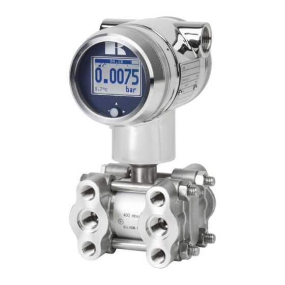
"Intelligent" Differential pressure transmitter
Read the recommendations and warnings in this manual before the instrument is installed. For personal
safety, optimal use and maintenance of the Series DP-4000, these instructions should be studied carefully.
Manufactured by:
www.klay-instruments.com
INSTRUCTION MANUAL
SERIES DP-4000
Nijverheidsweg 5
P.O. Box 13
Tel: +31-521-591550
Fax: +31 -521-592046
7991 CZ DWINGELOO
7990 AA DWINGELOO
The Netherlands
E-mail:
info@klay.nl
Advertisement
Table of Contents

Subscribe to Our Youtube Channel
Related Manuals for KLAY-INSTRUMENTS DP-4000 Series


Summary of Contents for KLAY-INSTRUMENTS DP-4000 Series
- Page 1 Read the recommendations and warnings in this manual before the instrument is installed. For personal safety, optimal use and maintenance of the Series DP-4000, these instructions should be studied carefully. Manufactured by: Nijverheidsweg 5 7991 CZ DWINGELOO P.O. Box 13 7990 AA DWINGELOO Tel: +31-521-591550 The Netherlands www.klay-instruments.com Fax: +31 -521-592046 E-mail: info@klay.nl...
-
Page 2: Table Of Contents
Instruction manual Series DP-4000 CONTENT INTRODUCTION........................3 DESCRIPTION SERIES DP-4000 ........................3 DESCRIPTION SERIES DP-4000 with separate diaphragm seals ..............3 DRAIN AND VENT VALVES ........................... 3 DIMENSIONAL DRAWINGS ....................4 APPLICATIONS ............................5 INSTALLING THE TRANSMITTER ..................... 6 TRANSMITTER HOUSING (Fully rotatable) ....................6 MANIFOLDS (Optional) .......................... -
Page 3: Introduction
Instruction manual Series DP-4000 1. INTRODUCTION The Series DP-4000 is a high-end pressure, differential pressure and flow transmitter based upon a piezoresistive silicon sensor, with a very high burst pressure. The sensor element is mounted in a stainless steel body. Pressure on the sensor element creates a very small deflection of the silicon substrate and bridge network. -
Page 4: Dimensional Drawings
Instruction manual Series DP-4000 2. DIMENSIONAL DRAWINGS DP-4000 Front view: Transparent cover, option “I” (extra price) Description Material Description Material ① Cover AISI 304 ⑥ O-Ring EPDM ② Display with navigation button ⑦ Electronic housing AISI 304 ③ Cover AISI 304 ⑧... -
Page 5: Applications
Instruction manual Series DP-4000 DP-4000 - Wall mounting * As standard the DP-4000 will be supplied with two cable entries M20 x 1.5. A cable gland can be supplied on request (extra price). 2.1 APPLICATIONS The Series DP-4000 can be used in wide variety of applications such as differential pressure, level and flow measurement. -
Page 6: Installing The Transmitter
Instruction manual Series DP-4000 3. INSTALLING THE TRANSMITTER The Diaphragm, Flange or separate diaphragm seals of the transmitter are protected with a special protection cap. It is advisable to only remove this protection until installation takes place. Do not damage the diaphragm, capillaries or any part of the process connection. -
Page 7: Wiring
Instruction manual Series DP-4000 3.7 WIRING Under the cover you will find the terminal board. ③ Illustrative side view Insert the wires into the connector and push the lever down by hand. The figure above shows the wiring connection of the transmitter. The 2-wires must be connected to + and - on the terminal board. -
Page 8: Remaining
Instruction manual Series DP-4000 4. REMAINING 4.1 EXTERNAL LOAD External loads must be placed in the negative side of the 2-wire loop. The minimum power supply is based on the total circuit resistance. The maximum external load (RI max.) for 24 Vdc will be 600 Ω (Ohm). At a higher power supply, the external load can be up to max. -
Page 9: Intrinsically Safe (Option Ex)
Instruction manual Series DP-4000 4.4 INTRINSICALLY SAFE (Option Ex) The Series DP-4000 is also available for intrinsically safe for use in zone 0. ATEX – KIWA 15ATEX0031 X IECEx – KIWA 15.0014X II 1G Ex ia IIC T5…T4 Ga (-20 < T <... -
Page 10: Graphic Display And Navigation Button
Instruction manual Series DP-4000 5. GRAPHIC DISPLAY AND NAVIGATION BUTTON The Series 4000 has a multifunctional display where different values can be displayed simultaneously. The display is equipped with a backlight. The entire menu is controlled by a navigation button. The navigation button has the following possibilities of movement: up, down, left, and right. -
Page 11: Summary Programming Points
Instruction manual Series DP-4000 5.1 GRAPHIC DISPLAY READOUT When the transmitter is powered, a flash screen with the name of the transmitter (Series 4000) and the software version appears for a few seconds. After this, the home screen will show the measured value as set in the factory. -
Page 12: Explanation Programming Points
Instruction manual Series DP-4000 6. EXPLANATION PROGRAMMING POINTS ZERO ADJUSTMENT (ZERO, 4 mA) The transmitter is set to 0 psi at atmospheric pressure. The ZERO can be adjusted at a lower or higher point. This will be explained step by step by an example. Example: Increase ZERO till 100 mbar. -
Page 13: Cancel Mounting Position Effect (4 Ma)
Instruction manual Series DP-4000 1. Navigate to program point P102, and push the button to enter the menu. 2. Choose Use process, and push to confirm. The transmitter will display the actual measured value. 3. Push the navigation button to confirm, and select to save the setting. -
Page 14: Damping Adjustment
Instruction manual Series DP-4000 DAMPING ADJUSTMENT The transmitter has an adjustable damping between 0.00 to 25.00 seconds. Factory setting = 0.00 seconds 1. Navigate to program point P106 – DAMPING, and push the navigation button to enter the menu. 2. Two choices appear on the screen: Set and Reset 3. -
Page 15: Readout
Instruction manual Series DP-4000 By choosing Readout the last measured minimum and maximum temperature values of process and ambient appear. For the process temperature, a new value is stored in a change of temperature more than 2 °C. For the ambient temperature this is 5 °C. By choosing Reset the previous stored values will be deleted. -
Page 16: Tank Linearization
Instruction manual Series DP-4000 The status on the display changes to Active and the current simulation is started for the selected step. Push the navigation button to de-activate the current simulation. Move the navigation button to the left to go back and leave this menu. 4. - Page 17 Instruction manual Series DP-4000 LINEARIZATION HORIZONTAL TANK (WITH FLAT END) 1. Navigate to Hor. Tank. with the navigation button, and push to confirm. 2. Two choices appear on the screen: Input and Simulate 3. Select Input, and push to confirm. 4.
- Page 18 Instruction manual Series DP-4000 LINEARIZATION HORIZONTAL TANK WITH A PARABOLIC END (CYLINDRICAL OR ELLIPTIC) 1. Navigate to Hor. Tank. with the navigation button, and push to confirm. 2. Two choices appear on the screen: Input and Simulate 3. Select Input, and push to confirm. 4.
- Page 19 Instruction manual Series DP-4000 LINEARIZATION VERTICAL TANK WITH A CONICAL BOTTOM 1. Navigate to Vert. Cone. with the navigation button, and push to confirm. 2. Two choices appear on the screen: Input and Simulate 3. Select Input, and push to confirm. 4.
- Page 20 Instruction manual Series DP-4000 6. Select to save the setting. 7. The transmitter will return to the main menu. SIMULATION After linearization is entered and stored, it is possible to perform a simulation based on the entered value’s. Based on the value entered in mWC, the transmitter will display the number of hectoliters (on the basis of the specified linearization values).
- Page 21 Instruction manual Series DP-4000 FREE LINEARIZATION FREE LINEARIZATION IN PROCESS 1. Navigate to program point P111 – TANK LIN, and push to confirm. 2. Navigate to Free lin. with the navigation button, and push to confirm. 3. Two choices appear on the screen: Measured and Manual 4.
- Page 22 Instruction manual Series DP-4000 FREE LINEARIZATION MANUALLY When it is not possible to enter and measure for a linearization in an actual process condition, a free linearization can be configured manually. Known measurements values and volumes must be entered manually in the transmitter. 1.
-
Page 23: Burst Mode
Instruction manual Series DP-4000 Save: When all desired measurements are completed and all parameters have been set, the linearization must be saved. Push the navigation button to the left to Exit and select to save the linearization. The transmitter will return to the main menu. WARNING AND PRECAUTIONS ... -
Page 24: Information
Instruction manual Series DP-4000 This value can be set from 0.5 to 3600 seconds. Select Min Time to set the minimum amount of time when the message will be send. This value can be set from 0.5 to 3600 seconds. Enter the preferred value, and push to confirm. - Page 25 Instruction manual Series DP-4000 Cut off: The Square root function can be enabled with an adjustable cut off value between 0 and 20%. The cut off adjustment prevents high gain on low values from the Square Root extraction. The diagram on the left shows a cut off adjustment at 20 %.
-
Page 26: Factory
Instruction manual Series DP-4000 Mass Flow units Unit Description Grams per second Grams per minute Grams per hour kg/s Kilograms per second kg/m Kilograms per minute kg/h Kilograms per hour kg/d Kilograms per day Metric tons per minute Metric tons per hour Metric tons per day lb/s Pounds per second... -
Page 27: Programming The Serie Dp-4000
Instruction manual Series DP-4000 7. PROGRAMMING THE SERIE DP-4000 7.1 PROGRAMMING WITH HAND HELD TERMINAL When using HART® or a Hand Held Terminal (HHT), a minimum resistance of 250 Ω must be present in the loop of the 2-wire system. This is necessary for proper communication (see drawing below). -
Page 28: Rotatable Display
Instruction manual Series DP-4000 7.2 ROTATABLE DISPLAY The display from Series 4000 is fully rotatable. To rotate the display, place a small screw driver into the recess on top of the display. Turn it by hand by moving the screw driver into the desired direction, use the other hand to guide this movement to avoid any damages. -
Page 29: Specifications
Instruction manual Series DP-4000 SPECIFICATIONS Manufacturer Klay Instruments Instrument Series DP-4000 Output 4-20 mA HART® Protocol Standard : 12 – 36 Vdc Ex : 12 – 30 Vdc Power Supply HART® : 17 – 36 Vdc (Standard) min. 250 Ω 17 –... -
Page 30: Precautions And Warnings
(technical field) and therefore does not warrant the suitability of its product for the application selected by the customer. Manufactured by: Nijverheidsweg 5 7991 CZ DWINGELOO P.O. Box 13 7990 AA DWINGELOO Tel: +31-521-591550 The Netherlands www.klay-instruments.com Fax: +31 -521-592046 E-mail: info@klay.nl Appendix: EU-Declaration of conformity. EN-DP-4000/04-2020/05 Page 30... - Page 31 Instruction manual Series DP-4000 EN-DP-4000/04-2020/05 Page 31...
Need help?
Do you have a question about the DP-4000 Series and is the answer not in the manual?
Questions and answers