Table of Contents
Advertisement
Quick Links
INSTRUCTION MANUAL
"Intelligent" Differential pressure transmitter
SERIES DP-4000
PROFIBUS PA
• Warning •
Read the recommendations and warnings in this manual before the instrument is installed. For personal
safety, optimal use and maintenance of the Series DP-4000, these instructions should be studied carefully.
Advertisement
Table of Contents

Related Manuals for KLAY-INSTRUMENTS DP-4000 Series


Summary of Contents for KLAY-INSTRUMENTS DP-4000 Series
- Page 1 INSTRUCTION MANUAL "Intelligent" Differential pressure transmitter SERIES DP-4000 PROFIBUS PA • Warning • Read the recommendations and warnings in this manual before the instrument is installed. For personal safety, optimal use and maintenance of the Series DP-4000, these instructions should be studied carefully.
-
Page 2: Table Of Contents
Instruction manual Series DP-4000-PROFIBUS® PA CONTENT INTRODUCTION ........................3 DESCRIPTION SERIES DP-4000 ........................3 DESCRIPTION SERIES DP-4000 with separate diaphragm seals ............... 3 DRAIN AND VENT VALVES ..........................3 DIMENSIONAL DRAWINGS ....................... 4 APPLICATIONS ......................... 5 INSTALLING THE TRANSMITTER ....................6 TRANSMITTER HOUSING (Fully rotatable) ...................... -
Page 3: Introduction
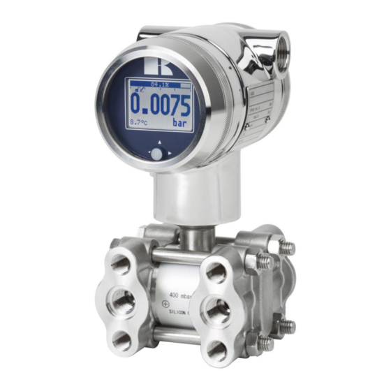
Instruction manual Series DP-4000-PROFIBUS® PA INTRODUCTION The Series DP-4000 is a high-end pressure, differential pressure and flow transmitter based upon a piezoresistive silicon sensor, with a very high burst pressure. The sensor element is mounted in a stainless steel body. Pressure on the sensor element creates a very small deflection of the silicon substrate and bridge network. -
Page 4: Dimensional Drawings
Instruction manual Series DP-4000-PROFIBUS® PA DIMENSIONAL DRAWINGS DP-4000 Front view: Transparent cover, option “I” (extra price) Description Material Description Material ① Cover SS 304 ⑥ O-Ring EPDM ② Display with navigation button ⑦ Electronic housing SS 304 ③ Cover SS 304 ⑧... -
Page 5: Applications
Instruction manual Series DP-4000-PROFIBUS® PA DP-4000 Wall mounting * As standard the DP-4000 will be supplied with two cable entries M20 x 1,5. A cable gland can be supplied on request (extra costs). APPLICATIONS The Series DP-4000 can be used in wide variety of applications such as differential pressure, level and flow measurement. -
Page 6: Installing The Transmitter
Instruction manual Series DP-4000-PROFIBUS® PA INSTALLING THE TRANSMITTER The Diaphragm, Flange or separate diaphragm seals of the transmitter are protected with a special protection cap. It is advisable to only remove this protection until installation takes place. Do not damage the diaphragm, capillaries or any part of the process connection. Do not dismantle the process connection (Sensor body). -
Page 7: Profibus Pa Cable
Instruction manual Series DP-4000-PROFIBUS® PA PROFIBUS PA CABLE Under the cover you will find the terminal board. Special PROFIBUS® cable must be used for proper ③ communication. For further detailed description of cable selection, see "Guidelines for planning and commissioning PROFIBUS DP/PA" and "PROFIBUS PA User and Installation Guideline" both on www.profibus.com and IEC 61158-2 on www.iec.ch. -
Page 8: Grounding
Instruction manual Series DP-4000-PROFIBUS® PA The wiring terminals can be operated without a screwdriver. The opening levers of the terminals can be lifted and pressed down by hand. Lift the opening levers of the terminals and insert the corresponding wires. Press down the levers by hand, the terminal spring will close and the wire is clamped. -
Page 9: Graphic Display And Navigation Button
Instruction manual Series DP-4000-PROFIBUS® PA GRAPHIC DISPLAY AND NAVIGATION BUTTON The DP-4000 has a multifunctional display where different values can be displayed simultaneously. The display is equipped with a backlight. The entire menu is controlled by a navigation button. The navigation button has the following possibilities of movement: up, down, left, and right. -
Page 10: Summary Programming Points
Instruction manual Series DP-4000-PROFIBUS® PA GRAPHIC DISPLAY READOUT When the transmitter is powered, a startup screen with the name of the transmitter (Series 4000) and the software version appear for a few seconds. The PROFIBUS® address is shown at the bottom of the display. -
Page 11: Explanation Programming Points
Instruction manual Series DP-4000-PROFIBUS® PA EXPLANATION PROGRAMMING POINTS 6.1 ZERO ADJUSTMENT The transmitter is set to 0 mbar at atmospheric pressure. The ZERO can be adjusted at a lower or higher point. This will be explained step by step by an example. Example: Increase ZERO till 100 mbar. -
Page 12: Cancel Mounting Position Effect
Instruction manual Series DP-4000-PROFIBUS® PA 6.3 CANCEL MOUNTING POSITION EFFECT All transmitters are vertically calibrated. If the transmitter is installed horizontally, the transmitter has a small mounting position effect on the zero. The pressure value displayed, will be for example 0,002 mbar instead of 0,000 mbar. This effect can be neutralized within this menu. -
Page 13: Language
Instruction manual Series DP-4000-PROFIBUS® PA 2. Two choices appear on the screen: Set and Reset 3. Make a choice and push to confirm. Choosing Set allows a value to be set between 0,00 and 25,00 seconds. Select Set, and push the button to confirm. ... -
Page 14: Readout
Instruction manual Series DP-4000-PROFIBUS® PA Select Unit to enter the engineering unit code. o With option Set manual the current scaling configuration (Profibus output) is shown. Set manual should only be used for units not supported by the DP-4000, or when a different scaling then the local readout is needed on the Profibus output. -
Page 15: Tank Linearization
Instruction manual Series DP-4000-PROFIBUS® PA Cubic meter = Number of cubic meters (in combination with linearization P110) Liter = Number of liters (only possible in combination with linearization P110) Kilogram = Number of kilograms (only possible in combination with linearization P110) After selecting this readout the Specific Gravity of the medium (SG = g/cm ) must be entered with a value between 0.2 and 4.0 g/cm... - Page 16 Instruction manual Series DP-4000-PROFIBUS® PA LINEARIZATION HORIZONTAL TANK (WITH FLAT END) 1. Navigate to Hor. Tank. with the navigation button, and push to confirm. 2. Two choices appear on the screen: Input and Simulate 3. Select Input, and push to confirm. 4.
- Page 17 Instruction manual Series DP-4000-PROFIBUS® PA LINEARIZATION HORIZONTAL TANK WITH A PARABOLIC END (CYLINDRICAL OR ELLIPTIC) 1. Navigate to Hor. Tank. with the navigation button, and push to confirm. 2. Two choices appear on the screen: Input and Simulate 3. Select Input, and push to confirm. 4.
- Page 18 Instruction manual Series DP-4000-PROFIBUS® PA 1. Navigate to Vert. Sphere. with the navigation button, and push to confirm. 2. Two choices appear on the screen: Input and Simulate 3. Select Input, and push to confirm. 4. Six choices appear on the screen: Display Drawing Explanation...
- Page 19 Instruction manual Series DP-4000-PROFIBUS® PA LINEARIZATION VERTICAL TANK WITH A SPHERICAL BOTTOM 1. Navigate to Vert. Cone. with the navigation button, and push to confirm. 2. Two choices appear on the screen: Input and Simulate 3. Select Input, and push to confirm. 4.
- Page 20 Instruction manual Series DP-4000-PROFIBUS® PA LINEARIZATION VERTICAL TANK WITH A TRUNCATED BOTTOM 1. Navigate to Vert. Trunc. with the navigation button, and push to confirm. 2. Two choices appear on the screen: Input and Simulate 3. Select Input, and push to confirm. 4.
- Page 21 Instruction manual Series DP-4000-PROFIBUS® PA FREE LINEARIZATION FREE LINEARIZATION IN PROCESS 1. Navigate to program point P110 – TANK LIN, and push to confirm. 2. Navigate to Free lin. with the navigation button, and push to confirm. 3. Two choices appear on the screen: Measured and Manual 4.
- Page 22 Instruction manual Series DP-4000-PROFIBUS® PA FREE LINEARIZATION MANUALLY When it’s not possible to enter and measure for a linearization in an actual process condition, a free linearization can be configured manually. Known measurements values and volumes must be entered manually in the transmitter. 1.
-
Page 23: Information
Instruction manual Series DP-4000-PROFIBUS® PA Save: When all desired measurements are completed and all parameters have been set, the linearization must be saved. Push the navigation button to the left to Exit and select save the linearization. The transmitter will return to the main menu. WARNING AND PRECAUTIONS ... -
Page 24: Pa Address
Instruction manual Series DP-4000-PROFIBUS® PA 6.13 PA ADDRESS In this menu a PA Address from 2 till 126 can be selected. 1. Navigate to program point P113 - PA Address and push the navigation button to enter the menu. 2. Select the address with the navigation button and push to confirm. Select to save the setting. - Page 25 Instruction manual Series DP-4000-PROFIBUS® PA Liters per second Ml/d Million liters per day ft³/s Cubic feet per second ft³/d Cubic feet per day m³/s Cubic meters per second m³/d Cubic meters per day iGal/h Imperial gallons per hour iGal/d Imperial gallons per day m³/h Normal cubic meter per hour (MKS System) Normal liter per hour (MKS System)
-
Page 26: Profibus® Pa
Instruction manual Series DP-4000-PROFIBUS® PA PROFIBUS® PA PA INTERFACE The DP-4000-PROFIBUS PA is developed as a PROFIBUS® Slave device. A slave device is a addressable peripheral device which reads process information and delivers output information to the Master device in the PROFIBUS® system. The Series 4000 is developed for Profibus PA Profile V3.02 and is backwards compatible with Profile version V3.01. - Page 27 Instruction manual Series DP-4000-PROFIBUS® PA Physical Block Parameters (Slot 0) In the table below the Physical Block parameters. Index Name Type Description BLOCK_OBJECT Record Block object Reserved Unsigned8 Block_Object Unsigned8 0x01, physical block Parent_Class Unsigned8 0x01, Transmitter Class Unsigned8 250, not used Dev_Rev Unsigned16 Dev_Rev_Comp...
- Page 28 Instruction manual Series DP-4000-PROFIBUS® PA DEVICE_MESSAGE OctetString(32) DEVICE_INSTAL_DATE OctetString(16) Optional parameter LOCAL_OP_ENA isn't NULL_PARAM implemented IDENT_NUMBER_SELECT Optional parameter HW_WRITE_PROTECTION isn't NULL_PARAM implemented Indicates optional features implemented in the device and the status of these features which FEATURE Record indicates if the feature is supported or not supported.
- Page 29 Instruction manual Series DP-4000-PROFIBUS® PA Actual_mode Unsigned8 Actual mode Permitted_mode Unsigned8 Permitted mode Normal_mode Unsigned8 Normal mode ALARM_SUM Record Current OctetString(2) Current alarm Unacknowledged OctetString(2) Unacknowledged alarm Unreported OctetString(2) Unreported alarm Disabled OctetString(2) Disabled alarm PRIMARY_VALUE Record Primary value and status (Pressure) Value Float Primary value...
- Page 30 Instruction manual Series DP-4000-PROFIBUS® PA Bitmapped structure Bit 0 = Reverse Output Bit 1 = Secondary display reading DEVICE SETTINGS Unsigned16 Bit 2-3 = Backlight Bit 4-6 = Language Bit 7-10 = Primary display reading Bit 11-15 = Reserved RESERVED Unsigned16 RESERVED Unsigned16...
- Page 31 Instruction manual Series DP-4000-PROFIBUS® PA BATCH Record Batch structure Identifies a certain batch to allow assignment of Batch_ID Unsigned32 equipment-related information (e.g. faults, alarms ...) to the batch Unsigned16 No. of Recipe Unit Procedure or of Unit Operation Unsigned16 No. of Recipe Operation Phase Unsigned16 No.
-
Page 32: Ident Number
Instruction manual Series DP-4000-PROFIBUS® PA Subcode Unsigned16 Value Float LO_LO_ALM Record State of the lower limit of alarms Unacknowledged Unsigned8 Alarm_State Unsigned8 Time_Stamp TimeValue Subcode Unsigned16 Value Float For commissioning and test purposes the input value from the Transducer Block into the Analog SIMULATE Record Input Function Block AI-FB can be modified. -
Page 33: Engineering Units
Instruction manual Series DP-4000-PROFIBUS® PA ENGINEERING UNITS The following engineering units are supported by the Series 4000 Profibus PA. Index Unit Description 1132 megapascal 1133 kilopascal 1137 1138 mbar millibar 1140 atmosphere 1145 kgf/cm kilogram-force per square centimeter 1147 O (4°C) inch of water at 4 °C 1150 O (4°C) -
Page 34: Rotatable Display
Instruction manual Series DP-4000-PROFIBUS® PA ROTATABLE DISPLAY The display from the DP-4000 is fully rotatable. To rotate the display, place a small screw driver into the recess on top of the display. Turn it by hand by moving the screw driver into the desired direction, use the other hand to guide this movement to avoid any damages. -
Page 35: Specifications
Instruction manual Series DP-4000-PROFIBUS® PA SPECIFICATIONS Manufacturer Klay Instruments B.V. Instrument Series DP-4000 Profibus PA - Slave Profile V3.02 Output Floating point IEEE754 Power Supply 12 - 30 Vdc Transmission speed 31.25 kb/sec Current consumption 13 mA ± 1 mA Fault current 13 mA ±... -
Page 36: Precautions And Warnings
Instruction manual Series DP-4000-PROFIBUS® PA PRECAUTIONS AND WARNINGS Check if the specifications of the transmitter meet the needs of the process conditions When the Series DP-4000 is used as a level transmitter, be aware of the place where the transmitter is mounted. Here are some suggestions: DO NOT mount a level transmitter in- or near filling or discharging pipes.
Need help?
Do you have a question about the DP-4000 Series and is the answer not in the manual?
Questions and answers