Table of Contents
Advertisement
Quick Links
• Warning •
Read the recommendations and warnings in this manual before the instrument is installed. For personal safety,
optimal use and maintenance of the temperature transmitters, these instructions should be studied carefully.
KLAY-INSTRUMENTS B.V.
EN-4000-TT-PROFIBUS-PA-09-2021-00
INSTRUCTION MANUAL
SERIES TT4000
PROFIBUS PA
"Intelligent" Temperature transmitter
Nijverheidsweg 5
P.O. Box 13
7990 AA Dwingeloo
The Netherlands
Tel: +31-521-591550
E-mail:
info@klay.nl
Internet:
www.klay.nl
1
Advertisement
Table of Contents

Subscribe to Our Youtube Channel
Related Manuals for KLAY-INSTRUMENTS TT4000 Series


Summary of Contents for KLAY-INSTRUMENTS TT4000 Series
- Page 1 Read the recommendations and warnings in this manual before the instrument is installed. For personal safety, optimal use and maintenance of the temperature transmitters, these instructions should be studied carefully. Nijverheidsweg 5 Tel: +31-521-591550 P.O. Box 13 E-mail: info@klay.nl 7990 AA Dwingeloo Internet: www.klay.nl KLAY-INSTRUMENTS B.V. The Netherlands EN-4000-TT-PROFIBUS-PA-09-2021-00...
-
Page 2: Table Of Contents
CONTENTS INTRODUCTION........................3 DIMENSIONAL DRAWINGS ....................4 INSTALLING THE TRANSMITTER ..................... 6 INSTALLING WELD-ON NIPPLE ........................6 CALIBRATION ................... Fout! Bladwijzer niet gedefinieerd. PROFIBUS PA CABLE ............................ 6 WIRING ............................... 7 GROUNDING ............................... 8 TERMINATION ............................8 REMAINING .......................... 8 CE / EMC-RULES .................. -
Page 3: Introduction
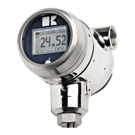
INTRODUCTION The SERIES TT-4000 Profibus PA is a complete Stainless Steel temperature transmitter, based on a Pt100 element (⅓ DIN Class B). The range of standard elements can be set from -20 until 200 and -40 until 400°C. Other ranges are available on request. The Pt100 element is mounted in a stainless steel welding nipple (sensor position 9). -
Page 4: Dimensional Drawings
DIMENSIONAL DRAWINGS Series TT-4000 Front view: Transparent cover, option “I” (extra price) Description Material Description Material ① Cover SS 304 ⑧ Extended connection SS 316 ② Display with navigation button ⑨ Process connection SS 304 ③ Cover with venting SS 304 ⑩... - Page 5 Series TT-4000 - Remote Description Material Description Material ① Cover SS 304 ⑧ Extended connection SS 316 ② Display with navigation button ⑨ M12 Connector SS 304 ③ Cover with venting SS 304 ⑬ M20 x 1.5 cable entry (without gland) * ④...
-
Page 6: Installing The Transmitter
INSTALLING THE TRANSMITTER The diaphragm of the transmitter is protected with a special protection cap. Protect the diaphragm until installation takes place. Do not damage or bend the temperature sensor. INSTALLING WELD-ON NIPPLE A certified welder should perform the installation of the weld-on nipple. Weld with Argon, MIG or TIG, with the smallest welding pin possible. -
Page 7: Wiring
Type A Technical specification: Impedance: 35 up to 165 Ohm at frequencies from 3 to 20 Mhz. Cable capacity: < 30 pF per meter. Core diameter: > 0,34 mm², corresponds to AWG 22. Cable type: Twisted pair cable. 1x2 or 2x2 or 1x4 lines. ... -
Page 8: Grounding
GROUNDING The transmitter must always be connected to ground. In case the process connection is already connected to ground (e.g. by the tank or pipe line) do not connect the instrument to ground. Please ensure that the instrument is not connected to ground twice to prevent an “Earth loop”. TERMINATION Termination of the bus prevents signal reflections on the PROFIBUS®... -
Page 9: Graphic Display And Navigation Button
GRAPHIC DISPLAY AND NAVIGATION BUTTON The Series 4000 has a multifunctional display where different values can be displayed simultaneously. The display is equipped with a backlight. The entire menu is controlled by a navigation button. The navigation button has the following possibilities of movement: up, down, left, and right. The navigation button needs to be pushed when conformation or saving is needed. -
Page 10: Graphic Display Readout
GRAPHIC DISPLAY READOUT When the transmitter is powered, a flash screen with the name of the transmitter (Series 4000) and the software version appear for a few seconds. The PROFIBUS® address is shown at the bottom of the display. As standard (Unconfigured) the address is 126. This address is used for configuration and commissioning purposes only. -
Page 11: Explanation Programming Points
EXPLANATION PROGRAMMING POINTS 6.1 ZERO ADJUSTMENT (ZERO, 0%) P101 The transmitter is set to 0 °C at 0%. Zero Value The ZERO can be adjusted at a lower or higher point. This will be explained step by step by an example. Example: Increase ZERO till +10 °C. -
Page 12: Pa Address
3. Push the navigation button to confirm, and select to save the setting. 6.3 PA ADDRESS P103 In this menu a PA Address from 2 till 126 can be selected. PA Address 1. Navigate to program point P103 - PA Address and push the navigation button to enter the menu. 2. -
Page 13: Damping Adjustment
P106 6.6 DAMPING ADJUSTMENT Damping The transmitter has an adjustable damping between 0,00 to 25,00 seconds. Factory setting = 0,00 seconds 1. Navigate to program point P106 – DAMPING, and push the navigation button to enter the menu. 2. Two choices appear on the screen: Set and Reset 3. - Page 14 temperature this is 5 ̊ C. By choosing Reset the previous stored values will be deleted. Sec. Value: Four choices appear on the screen for the secondary readout on the main screen, Unit, Rate and Ambient Temperature. PA_OUT_SCALE: On this menu scaling options for analog Inpu Block (profibus Output) can be configurd locally on the transmitter.
-
Page 15: Readout
Example Percentage: Analog input block Slot 1 Index 27 OUT (record) Float, PV SCALE Engineering Units at 100% = 200.0 Float, PV SCALE Engineering Units at 0% = 0.0 Index 28 OUT_SCALE (record) Float, Engineering units at 100% = 100.0 Float, Engineering units at 0% = 0.0 Unsigned16, Units Index = 1001 Unsigned8, Decimal Point = 1... -
Page 16: Factory
PA version Profibus version 3.02 6.11 FACTORY P111 Only available for the manufacturer. 6.12 FACTORY P112 Only available for the manufacturer. EN-4000-TT-PROFIBUS-PA-09-2021-00... -
Page 17: Profibus® Pa
PROFIBUS® PA PA INTERFACE The Series 4000-PROFIBUS PA is developed as a PROFIBUS® Slave device. A slave device is a addressable peripheral device which reads process information and delivers output information to the Master device in the PROFIBUS® system. The Series 4000 is developed for Profibus PA Profile V3.02 and is backwards compatible with Profile version V3.01. - Page 18 Physical Block Parameters (Slot 0) In the table below the Physical Block parameters. Index Name Type Description BLOCK_OBJECT Record Block object Reserved Unsigned8 Block_Object Unsigned8 0x01, physical block Parent_Class Unsigned8 0x01, Transmitter Class Unsigned8 250, not used Dev_Rev Unsigned16 Dev_Rev_Comp Unsigned16 DD_Revision Unsigned16...
- Page 19 WRITE_LOCKING Unsigned16 Software write protection FACTORY_RESET Unsigned16 Parameter for the device resetting DESCRIPTOR OctetString(32) DEVICE_MESSAGE OctetString(32) DEVICE_INSTAL_DATE OctetString(16) Optional parameter LOCAL_OP_ENA isn't NULL_PARAM implemented IDENT_NUMBER_SELECT Optional parameter HW_WRITE_PROTECTION isn't NULL_PARAM implemented Indicates optional features implemented in the device and the status of these features which FEATURE Record indicates if the feature is supported or not...
- Page 20 ST_REV shall be incremented at least by one if at ST_REV Unsigned16 least one static parameter in the corresponding block has been modified TAG_DESC OctetString(32) STRATEGY Unsigned16 ALERT_KEY Unsigned8 TARGET_MODE Unsigned8 Target mode MODE_BLK Record Actual_mode Unsigned8 Actual mode Permitted_mode Unsigned8 Permitted mode Normal_mode...
- Page 21 RESERVED Float RESERVED Float RESERVED Float RESERVED Float RESERVED Float RESERVED Float (0: reset, 1: correct mounting effect with measured PV MOUNT CORRECTION Unsigned16 pressure) Bitmapped structure Bit 0 = Reverse Output Bit 1 = Secondary display reading DEVICE SETTINGS Unsigned16 Bit 2-3 = Backlight Bit 4-6 = Language...
- Page 22 STRATEGY Unsigned16 ALERT_KEY Unsigned8 TARGET_MODE Unsigned8 Target mode MODE_BLK Record Actual_mode Unsigned8 Actual mode Permitted_mode Unsigned8 Permitted mode Normal_mode Unsigned8 Normal mode ALARM_SUM Record Current OctetString(2) Current alarm Unacknowledged OctetString(2) Unacknowledged alarm Unreported OctetString(2) Unreported alarm Disabled OctetString(2) Disabled alarm BATCH Record Batch structure...
-
Page 23: Ident Number
Unacknowledged Unsigned8 State of the upper limit of alarms. Alarm_State Unsigned8 Time_Stamp TimeValue Subcode Unsigned16 Value Float HI_ALM Record State of the upper limit of warnings Unacknowledged Unsigned8 Alarm_State Unsigned8 Time_Stamp TimeValue Subcode Unsigned16 Value Float LO_ALM Record State of the lower limit of warnings Unacknowledged Unsigned8 Alarm_State... -
Page 24: Engineering Units
ENGINEERING UNITS The following engineering units are supported by the Series 4000 Profibus PA. Index Unit Description 1001 ° C Celsius 1002 ° F Fahrenheit Additional units can be configured in the Analog Input Block. This is explained step by step by an example: ... -
Page 25: Rotatable Display
ROTATABLE DISPLAY The display of the Series TT-4000 is fully rotatable. To rotate the display, place a small screw driver into the recess on top of the display. Turn it by hand by moving the screw driver into the desired direction, use the other hand to guide this movement to avoid any damages. -
Page 26: Specifications
SPECIFICATIONS Manufacturer Klay Instruments B.V. Instrument TT-4000 Output PA 3.02 Standard: 12 – 36 Vdc Power Supply Accuracy ° C Ambient Temperature Standard -20 °C to 70 °C (-4 °F to 158 °F) Damping 0,00 seconds to 25,00 seconds Standard: 0,00 seconds. Protection Grade IP66 Material... -
Page 27: Precautions And Warnings
PRECAUTIONS AND WARNINGS Check if the specifications of the transmitter meet the needs of the process conditions WELDING INFORMATION: When using the Series TT-4000 with weld-on nipple, the welding information on page 6 must be followed exactly. This is very important to prevent distortion of the weld-on nipples. It also prevents the screw thread from being deformed. - Page 28 EN-4000-TT-PROFIBUS-PA-09-2021-00...
Need help?
Do you have a question about the TT4000 Series and is the answer not in the manual?
Questions and answers