Table of Contents
Advertisement
Available languages
Available languages
Quick Links
PRZETWORNIK
TEMPERATURY I WILGOTNOŚCI
TEMPERATURE
AND HUMIDITY TRANSDUCER
AND HUMIDITY TRANSDUCER
P18(D)
INSTRUKCJA OBSŁUGI SZYBKI START
PL
USER'S MANUAL QUICK START
EN
Zeskanuj mnie
Zeskanuj kod
Scan the code
Pełna wersja instrukcji dostępna na
Full version of user's manual available at
www.lumel.com.pl
Advertisement
Table of Contents

Subscribe to Our Youtube Channel
Related Manuals for Lumel P18D


Summary of Contents for Lumel P18D
- Page 1 PRZETWORNIK TEMPERATURY I WILGOTNOŚCI TEMPERATURE AND HUMIDITY TRANSDUCER AND HUMIDITY TRANSDUCER P18(D) INSTRUKCJA OBSŁUGI SZYBKI START USER’S MANUAL QUICK START Zeskanuj mnie Zeskanuj kod Scan the code Pełna wersja instrukcji dostępna na Full version of user’s manual available at www.lumel.com.pl...
- Page 2 1. WYMAGANIA PODSTAWOWE, BEZPIECZEŃSTWO UŻYTKOWANIA W zakresie bezpieczeństwa użytkowania przetwornik odpo- wiada wymaganiom normy PN-EN 61010-1. Uwagi dotyczące bezpieczeństwa • Montażu i instalacji połączeń elektrycznych powinna dokonać osoba z uprawnieniami do montażu urządzeń elektrycznych. • Przed włączeniem przetwornika należy sprawdzić poprawność połączeń.
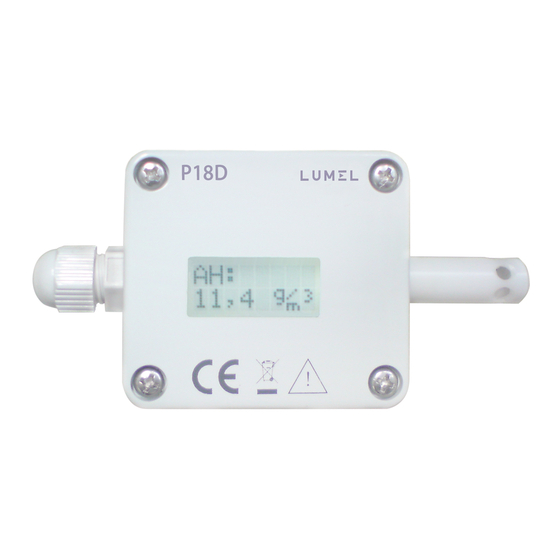
- Page 3 2.2. Schematy podłączeń zewnętrznych Patrz rysunek 3 i 4, strona 18. 3. OBSŁUGA Przetwornik P18D wyposażony jest w pole odczytowe 8x2 znaki z podświetleniem oraz jeden przycisk pojemnościowy umiejscowiony na obudowie przetwornika. Przetwornik P18 nie jest wyposażony w wyświetlacz ani w przycisk. Po podłączeniu przewodów, skręceniu obudowy i włączeniu zasilania przetwornik jest gotowy do pracy z nasta-...
- Page 4 3.1. Komunikaty po włączeniu zasilania przetwornika P18D Po podłączeniu sygnałów zewnętrznych i włączeniu zasilania, przetwornik wyświetla typ, aktualną wersję programu, numer seryjny oraz ustawione parametry komunikacyjne (adres, prędkość transmisji oraz tryb pracy). Po około 5 sekundach przetwornik automatycznie przechodzi do trybu pracy, w którym dokonuje pomiaru i przetwarzania na analo- gowy sygnał...
- Page 5 Opis symboli wyświetlanych przez przetwornik P18D znajduje się w tablicy 1. Tablica 1 Symbol Znaczenie Typ wielkości wyświetlanej na dolnym wierszu LCD - temperatura Typ wielkości wyświetlanej na dolnym wierszu LCD – wilgotność względna Typ wielkości wyświetlanej na dolnym wierszu LCD –...
- Page 6 • programowania parametrów komunikacyjnych (adres, prędkość, tryb) 3.4. Menu programowania parametrów przetwornika P18D Wejście w menu programowania odbywa się po naciśnięciu i przytrzymaniu przycisku pojemnościowego przez czas ok. 5 sek. Przy pierwszym wejściu w menu znacznik kierunku zmian zostanie ustawiony na - zwiększanie wartości;...
-
Page 7: Dane Techniczne
Rys. 8. Algorytm programowania parametrów przetwornika P18D 4. DANE TECHNICZNE Parametry podstawowe: - zakres pomiaru wilgotności względnej (RH): 0...100%, bez kondensacji - błąd podstawowy przetwarzania wilgotności: ± 2% zakresu dla RH = 10...90% ± 3% w pozostałym zakresie - histereza pomiaru wilgotności: ± 1% RH - podstawowy zakres pomiaru temperatury (T): -20...60°C... - Page 8 Wyjście cyfrowe RS-485: protokół transmisji: MODBUS; prędkość transmisji: 4800, 9600,19200,38400,57600 bit/s; tryb RTU: 8N2, 8E1, 8O1, 8N1; maksymalny czas odpowiedzi: 500 ms Wyjście analogowe: prądowe: 4...20 mA; napięciowe: 0...10 V; maksymalna rezystancja obciążenia wyjścia prądowego:100 ; minimalna rezystancja obciążenia wyjścia napięciowego: 1 k Znamionowe warunki użytkowania: zasilanie: 9...24 V a.c./d.c.;...
- Page 9 5. KOD WYKONAŃ Tablica 2 P18(D) - X Wyjścia analogowe - czujnik: bez wyjść, czujnik przy obudowie prądowe 4...20 mA, czujnik przy obudowie napięciowe 0...10V, czujnik przy obudowie bez wyjść, sonda na przewodzie 0,5 m prądowe 4...20 mA, sonda na przewodzie 0,5 m napięciowe 0...10V, sonda na przewodzie 0,5 m Wykonanie: standardowe...
-
Page 10: Basic Requirements, Operational Safety
1. BASIC REQUIREMENTS, OPERATIONAL SAFETY In terms of operational safety, the transducer meets the requi- rements of EN 61010-1 standard. Safety instructions • The assembly and the installation of the electrical connections may be carried out only by a duly qualified electrician. •... - Page 11 2.2. External connections diagram See fig. 3 and 4, page 18. 3. SERVICE The P18D transducer is equipped with a display field 8x2 characters with illumination and one capacitive button located on the housing. The P18 transducer is not equipped with a display or a button.
- Page 12 3.2. Description of the P18D transducer readout field The illuminated character LCD is a readout field in the trans- ducer P18D. The illumination is turned on after switching on the supply and after the capacitive button on the housing is pressed. The illumina- tion is automatically switched off after 30 sec.
- Page 13 Description of the symbols displayed by the P18D transducer is in the Table 1. Table 1 Symbol Meaning Type of the displayed value in the bottom line of the LCD - temperature Type of the displayed value in the bottom line...
- Page 14 • program communication parameters (address, baud rate, mode) 3.4. Programming parameters menu of the P18D transducer Enter the programming menu by pressing and holding the capacitive button for approx. 5 sec. When entering the menu a first time, changes direction marker is set to - increasing the value;...
-
Page 15: Technical Data
Fig. 8. Programming parameters algorithm of the P18D transducer 4. TECHNICAL DATA Basic parameters: - range of relative humidity measurement (RH): 0...100%, without condensation - basic error of humidity conversioni: ± 2% of the range for RH = 10...90% ±... - Page 16 RS-485 digital output: transmission protocol: MODBUS; baud rate: 4800, 9600,19200,38400,57600 bit/s; mode: RTU: 8N2, 8E1, 8O1, 8N1 max. response time: 300 ms Analog outputs: current: 4...20 mA; voltage: 0...10 V; max. load resi- stance of the current output: 100 min. load resistance of the voltage output: 1 k...
-
Page 17: Ordering Code
5. ORDERING CODE Table 2 P18(D) - X Analog outputs - sensor: without outputs, sensor on the housing current 4...20 mA, sensor on the housing voltage 0...10V, sensor on the housing without outputs, probe on the wire 0,5 m current 4...20 mA, probe on the wire 0,5 m voltage 0...10V, probe on the wire 0,5 m Version: standard... - Page 18 You should use a multiconductor round wire with exter- nal diameter from 3.5 mm up to 6 mm for electrical connections. Remove the display prior to connecting the wires in a screw terminal of the P18D transducer. Pass supplying wires through the packing and twist the packing seal in order to obtain the leaktightness.
- Page 19 Przetwornik bez wyjść analogowych Transducer without analog outputs Przetwornik WYJ 1 WYJ 1 OUT 1 OUT 1 z wyjściami prądowymi Transducer with current outputs WYJ 1 Przetwornik z wyjściami WYJ 1 OUT 1 OUT 1 napięciowymi Transducer with voltage outputs Rys.
- Page 20 LUMEL S.A. ul. Sulechowska 1, 65-022 Zielona Góra, Poland tel.: +48 68 45 75 100, fax +48 68 45 75 508 www.lumel.com.pl Informacja techniczna: tel.: (68) 45 75 306, 45 75 180, 45 75 260 e-mail: sprzedaz@lumel.com.pl Realizacja zamówień: tel.: (68) 45 75 207, 45 75 209, 45 75 218, 45 75 341 fax.: (68) 32 55 650...
Need help?
Do you have a question about the P18D and is the answer not in the manual?
Questions and answers