Table of Contents
Advertisement
Available languages
Available languages
Quick Links
Page 1 of 21
LP0308
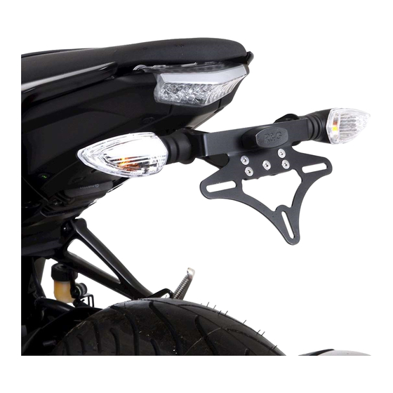
FITTING INSTRUCTIONS FOR LP0308BK LICENCE PLATE BRACKET
YAMAHA MT-125 2020-
This kit contains the items pictured and labelled over page.
Some parts may be shown for clarity of instructions only.
Do not proceed until you are sure all parts are present.
Please read all instructions before proceeding.
IF IN ANY DOUBT WHEN FITTING OUR PRODUCTS, CONSULT ONE OF OUR DEALERS
OR HAVE FITTED BY A QUALIFIED TECHNICIAN.
Please note that the way the kit is packed does not necessarily represent the way of
mounting to the bike.
In the event of rubber washers being used to hold components onto bolts,
these rubber washers can be thrown away.
DIGITAL COPIES OF THESE INSTRUCTIONS ARE AVAILABLE FROM
WWW.RG-RACING.COM
R&G
Unit
, Shelley's Lane, East Worldham, Alton, Hampshire, GU34 3AQ
1
Tel: +44 (0)
420 89007 Fax: +44 (0)
420 87301 www.rg-racing.com Email: info@rg-racing.com
1
1
Advertisement
Table of Contents

Subscribe to Our Youtube Channel
Related Manuals for R&G LP0308BK


Summary of Contents for R&G LP0308BK
- Page 1 Page 1 of 21 LP0308 FITTING INSTRUCTIONS FOR LP0308BK LICENCE PLATE BRACKET YAMAHA MT-125 2020- This kit contains the items pictured and labelled over page. Some parts may be shown for clarity of instructions only. Do not proceed until you are sure all parts are present.
-
Page 2: Tools Required
Page 2 of 21 LP0308 TOOLS REQUIRED GENERAL TORQUE SETTINGS Set of metric Allen keys to include M4 BOLT = 8Nm • 3, 4, 5 & 6mm. M5 BOLT = Set of metric sockets or spanners • to include 6, 8, 10 & 12mm. M6 BOLT = Phillips screwdriver. -
Page 3: Assembly Diagram
Page 3 of 21 LP0308 ASSEMBLY DIAGRAM 1 FITTING PICTURES Seat remove Picture 2 Picture 1 R&G Unit , Shelley’s Lane, East Worldham, Alton, Hampshire, GU34 3AQ Tel: +44 (0) 420 89007 Fax: +44 (0) 420 87301 www.rg-racing.com Email: info@rg-racing.com... - Page 4 Page 4 of 21 LP0308 Picture 3 Picture 4 Picture 5 Picture 6 R&G Unit , Shelley’s Lane, East Worldham, Alton, Hampshire, GU34 3AQ Tel: +44 (0) 420 89007 Fax: +44 (0) 420 87301 www.rg-racing.com Email: info@rg-racing.com...
- Page 5 Page 5 of 21 LP0308 Picture 8 Picture 7 Picture 10 Picture 9 Picture 11 Picture 12 R&G Unit , Shelley’s Lane, East Worldham, Alton, Hampshire, GU34 3AQ Tel: +44 (0) 420 89007 Fax: +44 (0) 420 87301 www.rg-racing.com Email: info@rg-racing.com...
-
Page 6: Fitting Instructions
Page 6 of 21 LP0308 FITTING INSTRUCTIONS To fit the R&G tail tidy, remove the seat from the bike using the key under the tail unit as • shown in Picture 1. Remove the 2 bolts also shown in Picture 1, using a 10mm socket or spanner. •... - Page 7 Page 7 of 21 LP0308 The R&G tail tidy can now be offered up to the mounting holes on the underside of the tail unit. • At this time route the cables through the hole where they were removed previously. Insert the M6 bolts and secure the tail tidy in place while reattaching the support bracket shown •...
- Page 8 Page 8 of 21 LP0308 NOTICE DE MONTAGE POUR LP0308BK SUPPORT DE PLAQUE YAMAHA MT-125 2020- E KIT CONTIENT LES ARTICLES ILLUSTRES ET ETIQUETES SUR LA PAGE ERTAINES PARTIES PEUVENT ETRE PRESENTES UNIQUEMENT POUR LA CLARTE DES INSTRUCTIONS E PAS PROCEDER AU MONTAGE TANT QUE VOUS N...
-
Page 9: Outils Requis
Page 9 of 21 LP0308 OUTILS REQUIS VALEURS DE SERRAGE Set of metric Allen keys to include M4 BOULON = 8Nm • 3, 4, 5 & 6mm. M5 BOULON = Set of metric sockets or spanners • to include 6, 8, 10 & 12mm. M6 BOULON = Phillips screwdriver. -
Page 10: Schéma D'assemblage
Page 10 of 21 LP0308 SCHÉMA D’ASSEMBLAGE 1 PHOTOS DE MONTAGE Clé pour retirer le siège Photo 2 Photo 1 R&G Unit , Shelley’s Lane, East Worldham, Alton, Hampshire, GU34 3AQ Tel: +44 (0) 420 89007 Fax: +44 (0) 420 87301 www.rg-racing.com Email: info@rg-racing.com... - Page 11 Page 11 of 21 LP0308 Photo 3 Photo 4 Photo 5 Photo 6 Photo 7 Photo 8 R&G Unit , Shelley’s Lane, East Worldham, Alton, Hampshire, GU34 3AQ Tel: +44 (0) 420 89007 Fax: +44 (0) 420 87301 www.rg-racing.com Email: info@rg-racing.com...
- Page 12 Page 12 of 21 LP0308 Photo 10 Photo 9 Photo 11 Photo 12 R&G Unit , Shelley’s Lane, East Worldham, Alton, Hampshire, GU34 3AQ Tel: +44 (0) 420 89007 Fax: +44 (0) 420 87301 www.rg-racing.com Email: info@rg-racing.com...
-
Page 13: Notice De Montage
Page 13 of 21 LP0308 NOTICE DE MONTAGE Pour installer le support R&G, retirez la selle de la moto à l'aide de la clé sous l'unité arrière • comme indiqué sur la photo 1. Retirez les 2 boulons également illustrés sur la photo 1, à l'aide d'une douille ou d'une clé de 10 •... - Page 14 Page 14 of 21 LP0308 Maintenant, le panneau latéral droit arrière peut être refixé en serrant d'abord les boulons • illustrés sur la photo 2, puis en serrant les vis illustrées sur la photo 1. Le siège peut ensuite être remis en place, en s'assurant qu'il s'enclenche et qu'il soit sécurisé •...
- Page 15 Page 15 of 21 LP0308 MONTAGEANLEITUNG FÜR LP0308BK KENNZEICHENHALTER YAMAHA MT-125 2020- Alle Kit-Teile sind auf den nachfolgenden Seiten abgebildet und gekennzeichnet. Die abgebildeten Teile dienen lediglich zur Erklärung. Überprüfen Sie zuerst, dass alle Teile vorhanden sind. Lesen Sie die Montageanleitung komplett durch, bevor Sie anfangen.
-
Page 16: Sie Benötigen Folgendes Werkzeug
Page 16 of 21 LP0308 SIE BENÖTIGEN FOLGENDES WERKZEUG: ALLGEM. ANZUGSDREHMOMENT Satz Inbusschlüssel inkl. 3, 4, 5 & 6mm M4 SCHRAUBE = 8Nm • Satz Steckschlüssel oder Schraubenschlüssel • M5 SCHRAUBE = inkl. 6, 8, 10 & 12mm Kreuzschlitzschraubenzieher • M6 SCHRAUBE = •... - Page 17 Page 17 of 21 LP0308 ZUSAMMENBAU – ZEICHNUNG BILDER - MONTAGE Sitz – Schlüssel entfernen Abbildung 2 Abbildung 1 R&G Unit 1, Shelley’s Lane, East Worldham, Alton, Hampshire, GU34 3AQ Tel: +44 (0)1420 89007 Fax: +44 (0)1420 87301 www.rg-racing.com Email: info@rg-racing.com...
- Page 18 Page 18 of 21 LP0308 Abbildung 3 Abbildung 4 Abbildung 5 Abbildung 6 Abbildung 8 Abbildung 7 R&G Unit 1, Shelley’s Lane, East Worldham, Alton, Hampshire, GU34 3AQ Tel: +44 (0)1420 89007 Fax: +44 (0)1420 87301 www.rg-racing.com Email: info@rg-racing.com...
- Page 19 Page 19 of 21 LP0308 Abbildung 10 Abbildung 9 Abbildung 11 Abbildung 12 MONTAGEANLEITUNG Um den R&G Kennzeichenhalter montieren zu können, entfernen Sie zuerst den Sitz (mit dem • Schlüssel unter dem Heck lösen) – siehe Abbildung 1. • Entfernen Sie die 2 Schrauben, die auch in Abbildung 1 abgebildet sind mit einem 10mm Steckschlüssel oder Schraubenschlüssel.
- Page 20 Page 20 of 21 LP0308 • Entfernen Sie vorsichtig die Kabel, die mit dem original Kennzeichenhalter verbunden sind, durch die kleine Öffnungen and der Unterseite des Hecks. Nachdem der original Kennzeichenhalter entfernt ist, muss nun der R&G Kennzeichenhalter • zusammengebaut werden, bevor er montiert werden kann. •...
- Page 21 Page 21 of 21 LP0308 CONSUMER NOTICE The catalogue description and any exhibition of samples are only broad indications of the Products and R&G may make design changes which do not diminish their performance or visual appeal and supplying them in such state shall conform to the order.
Need help?
Do you have a question about the LP0308BK and is the answer not in the manual?
Questions and answers