Advertisement
Quick Links
50-VFE-SMY62EN
ORIGINAL INSTRUCTIONS
Refer to Declaration of
Conformity for relevant
Instruction Manual
Directives
Solenoid operated 3 and 5 port valves
50-VFE/VPE-X60, 50-VFE3#90-X60 NAMUR
ATEX Classification:
-10°C ≤ Ta ≤ +40°C(+50°C)
II 2G Ex db IIC T6..(T5) Gb
Certificate reference: KEMA 09ATEX0024 X
'X' Special conditions of safe use apply, see section 1.2.
For ISO symbols see section 3.4.
The intended use of this product is to provide directional control to
pneumatic actuators (or similar industrial pneumatic equipment).
1 Safety Instructions
1.1 General safety instructions
These safety instructions are intended to prevent hazardous situations
and/or equipment damage. These instructions indicate the level of
potential hazard with the labels of "Caution," "Warning" or "Danger."
They are all important notes for safety and must be followed in addition
to International Standards (ISO/IEC)
*1)
, and other safety regulations.
*1)
ISO 4414: Pneumatic fluid power - General rules relating to systems.
ISO 4413: Hydraulic fluid power - General rules relating to systems.
IEC 60204-1: Safety of machinery - Electrical equipment of machines.
(Part 1: General requirements)
ISO 10218-1: Manipulating industrial robots -Safety. etc.
Refer to product catalogue, Operation Manual and Handling
Precautions for SMC Products for additional information.
Keep this manual in a safe place for future reference.
Caution indicates a hazard with a low level of risk which, if
Caution
not avoided, could result in minor or moderate injury.
Warning indicates a hazard with a medium level of risk
Warning
which, if not avoided, could result in death or serious injury.
Danger indicates a hazard with a high level of risk which, if
Danger
not avoided, will result in death or serious injury.
Warning
Always ensure compliance with relevant safety laws and
standards.
All work must be carried out in a safe manner by a qualified person in
compliance with applicable national regulations.
The product is only suitable for use in Zones 1 and 2.
Do not open when energised.
Do not energise both solenoids at the same time, as this can cause
higher surface temperatures than under normal operating conditions.
Do not refurbish the flameproof joints.
1 Safety Instructions - continued
Electrostatic charge may cause an explosion hazard.
Avoid any actions that cause the generation of electrostatic charge,
such as rubbing with a dry cloth on coating face of product.
Electrostatic charges on the non-metallic parts of the equipment shall
be avoided.
This product has components made of aluminium alloy. When
mounting this product, it must be installed such that, even in the event
of rare incidents, ignition sources due to impact and friction sparks are
excluded.
Use of 50-VFE3000/5000-X60 5-port valve as a 3-port valve
Series 50-VFE3000/5000-X60 valves can be used as normally closed
(N.C.) or normally open (N.O.) 3 port valves by closing one of the
cylinder ports (A or B) with a plug (see Table 1).
Note: Do not exceed the maximum specified operating frequency.
Plug position
2(B) port (CYL.1 port)
4(A) port (CYL.2 port)
Switching type
N.C.
N.O.
Single
Double
Table 1
1.2 Special conditions for safe use
Warning
The solenoid valves are provided with special fasteners of property
class A2-50.
The manufacturer shall be contacted for information regarding the
flameproof joints.
2 Specifications
2.1 General specifications
SERIES 50-VFE3000/5000-X60 SOLENOID VALVE
Series
50-VFE3000
50-VFE5000
Fluid
Air and inert gas
Operating
2 position single
0.15 to 0.9 MPa
pressure
3 position
range
2 position double
0.1 to 0.9 MPa
Ambient and fluid temperature
-10 to 50°C (T5)
(No freezing)
-10 to 40°C (T6)
Max. operating
2 position single
frequency
(1)
2 position double
1 Hz
3 position
Lubrication
Not required
Mounting position
Unrestricted
(2)
2
Impact/Vibration resistance
150/30 m/s
SERIES 50-VPE500/700-X60 SOLENOID VALVE
Fluid
Air and inert gas
Type of actuation
N.C or N.O. (convertible)
Pilot style
Internal pilot
External pilot
Supply
-101.2 kPa to
pressure
0.8 MPa
Operating pressure range
0.2 to 0.8 MPa
External pilot
0.2 to 0.8 MPa
pressure
Ambient and fluid temperature
-10 to 50°C (T5)
(No freezing)
-10 to 40°C (T6)
(1)
Max. operating frequency
1Hz
Lubrication
Not required
Mounting position
Unrestricted
Impact/Vibration resistance
(2)
150/30 m/s
2
2 Specifications - continued
SERIES 50-VFE3#90-X60 NAMUR SOLENOID VALVE
Fluid
Air and inert gas
Type of actuation
N.C or N.O. (convertible)
Operating pressure range
0.15 to 0.9 MPa
Ambient and fluid temperature
-10 to 50°C (T5)
(No freezing)
-10 to 40°C (T6)
Max. operating frequency
(1)
1Hz
Lubrication
Not required
Mounting position
NAMUR Interface
(2)
2
Impact/Vibration resistance
150/30 m/s
Note 1) Do not exceed the maximum specified operating frequency.
Note 2) Impact resistance: There should be no malfunction of the valve after testing
along the valve axis and at right angles to the valve and armature. Carry out each
test with the valve energised and de-energised (value at initial stage).
Vibration resistance: There should be no malfunction of the valve after testing using
a 8.3 to 2000Hz sweep along the valve axis and at right angles to the valve and
armature. Carry out each test with the valve energised and de-energised (value at
initial stage).
SERIES 50-VF3-#-X60 PILOT VALVE
External connection method
Metal conduit type/ (Cable gland type)
100, 200, 12, 24,
AC (50/60 Hz)
48, 110, 220, 240V
Coil rated voltage
DC
24, 12, 6, 48, 110V
Allowable voltage fluctuation
-15% to +10% of rated voltage
Coil insulation type
Type B
Inrush
9.1VA (50Hz) 7.8VA (60Hz)
Apparent power
AC
Holding
6.2VA (50Hz) 4.6VA (60Hz)
Power
3.5W
DC
consumption
3.9W (48, 110V)
Electric circuit
Non-polar type
Batch codes and Construction month:
The product control number is shown by two characters and two figures.
The character shows Year and Month of manufacturing.
Co nstructio n
P ro ductio n batch co des
Year / M o nth Jan Feb M ar A pr M ay Jun Jul A ug Sep Oct No v Dec
201 9
Xo
XP
XQ
XR
XS
XT XU
XV
XW XX
2020
yo
yP
yQ
yR
yS
yT
yU
yV
yW
yX
...
...
...
...
...
...
...
...
...
...
...
2024
Co
CP
CQ CR
CS
CT CU CV
CW CX
The figures show a serial number stamp.
This stamp indicates the year and month of production, the month of the
production request and the order in which work order has been
processed.
3 Installation
3.1 Installation
Warning
Do not install the product unless the safety instructions have been read
and understood.
3.2 Environment
Warning
The product is only suitable for use in Zones 1 and 2.
Do not use in an environment where corrosive gases, chemicals, salt
water or steam are present.
Do not expose to direct sunlight. Use a suitable protective cover.
Do not install in a location subject to vibration or impact in excess of
the product's specifications.
Do not mount in a location exposed to radiant heat that would result in
temperatures in excess of the product's specifications.
When the solenoid valve is mounted in a control panel or is energised
for a long time, make sure the ambient temperature is within the valve
specification range.
3 Installation - continued
3.3 Piping
Caution
Before connecting piping make sure to clean up chips, cutting oil, dust
etc.
When installing piping or fittings, ensure sealant material does not
enter inside the port. When using seal tape, leave 1 thread exposed
on the end of the pipe/fitting.
Tighten fittings to the specified tightening torque, see Table 2.
Thread
Tightening Torque (N•m)
M5
1 to 1.5
1/8
3 to 5
1/4
8 to 12
3/8
15 to 20
1/2
20 to 25
Table 2
3.4 ISO symbols
50-VPE5(7)42(R)
N.C.
N.O.
C.O.
50-VFE3/5000
5/2 Single
5/2 Double
Xy
XZ
yy
yZ
5/3 Closed
...
...
centre
Cy
CZ
5/3 Exhaust
centre
5/3 Pressure
centre
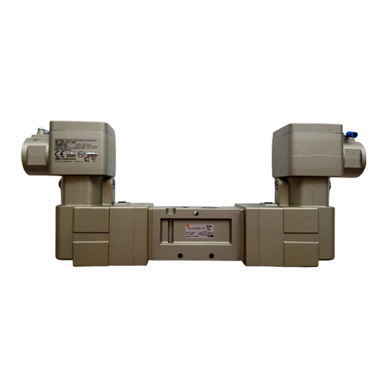
3.5 Electrical entry (see Figure 1)
The terminal box can be rotated 300° about plane 'A'.
Loosen screw 'C' and rotate the terminal box to the desired position.
Re-tighten screw to lock the terminal box in position.
The cover can be rotated 360° about plane 'B'.
Undo screw 'D' and rotate the cover to the desired position – there are
4 positions – in increments of 90°.
Re-assemble screw to lock the cover in place.
Page 1 of 4
Advertisement

Related Manuals for SMC Networks 50-VFE


Summary of Contents for SMC Networks 50-VFE
- Page 1 -10 to 50°C (T5) on the end of the pipe/fitting. Tighten fittings to the specified tightening torque, see Table 2. 50-VFE/VPE-X60, 50-VFE3#90-X60 NAMUR of rare incidents, ignition sources due to impact and friction sparks are (No freezing) -10 to 40°C (T6) Max.
- Page 2 50-VFE-SMY62EN 3 Installation - continued 3 Installation - continued 3 Installation - continued 3 Installation - continued After crimping, check the crimp by slightly pulling the insulated wire. Internal earthing: Use at least 2.63 mm or large wire Assembly of external ground terminal to cable ...
- Page 3 Not following proper maintenance procedures could cause the product to malfunction and lead to equipment damage. If handled improperly, compressed air can be dangerous. 50-VFE-X60 Valve mounting: Maintenance of pneumatic systems should be performed only by qualified personnel.
- Page 4 50-VFE-SMY62EN 7 Maintenance - continued 8 Limitations of Use 8.1 Limited warranty and Disclaimer/Compliance Requirements Refer to Handling Precautions for SMC Products. Warning Refer to the ATEX classification for the product. The product is suitable for use in ATEX Zones 1 and 2 applications only.
Need help?
Do you have a question about the 50-VFE and is the answer not in the manual?
Questions and answers