Table of Contents
Advertisement
Quick Links
56-VV5QC*1-TFL33-D
Installation and Maintenance Manual
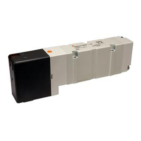
5 Port Solenoid Valve
Series 56-VQC1000/2000/4000
ATEX Marking Description
II 3G Ex nA IIB T4..T5 Gc
-10ºC
Ta
+50ºC
II 3D Ex tc IIIC T80..T86°C Dc IP67
Manifold with Serial Transmission System (56-EX500 or 56-EX250)
Refer to separate applicable documentation
Certificate reference: SMC 19.0030 X
For specific conditions of use see section 1.1.
1 Safety Instructions
This manual contains essential information for the protection of users and
others from possible injury and/or equipment damage.
Read this manual before using the product, to ensure correct handling,
and read the manuals of related apparatus before use.
Keep this manual in a safe place for future reference.
These instructions indicate the level of potential hazard by label of
"Caution", "Warning" or "Danger", followed by important safety
information which must be carefully followed.
To ensure safety of personnel and equipment the safety instructions in
this manual and the product catalogue must be observed, along with
other relevant safety practices.
Indicates a hazard with a low level of risk, which if
Caution
not avoided, could result in minor or moderate
injury.
Indicates a hazard with a medium level of risk,
Warning
which if not avoided, could result in death or
serious injury.
Indicates a hazard with a high level of risk, which
Danger
if not avoided, will result in death or serious
injury.
The compatibility of pneumatic equipment is the responsibility of the
person who designs the pneumatic system or decides its specifications.
Since the products specified here can be used in various operating
conditions, their compatibility with the specific pneumatic system must
be based on specifications or after analysis and/or tests to meet specific
requirements.
Only trained personnel should operate pneumatically operated
machinery and equipment.
Compressed air can be dangerous if an operator is unfamiliar with it.
Assembly, handling or repair of pneumatic systems should be performed
by trained and experienced personnel.
Do not service machinery/equipment or attempt to remove
components until safety is confirmed.
1) Inspection and maintenance of machinery/equipment should only be
performed after confirmation of safe locked-out control positions.
2) When equipment is to be removed, confirm the safety process as
mentioned above. Switch off air and electrical supplies and exhaust all
residual compressed air in the system.
1 Safety Instructions (continued)
3) Before machinery/equipment is re-started, ensure all safety measures to
prevent sudden movement of cylinders etc. (Supply air into the system
gradually to create back pressure, i.e. incorporate a soft-start valve).
Do not use this product outside of the specifications. Contact SMC
if it is to be used in any of the following conditions:
1) Conditions and environments beyond the given specifications, or if the
product is to be used outdoors.
2) Installations in conjunction with atomic energy, railway, air navigation,
vehicles, medical equipment, food and beverage, recreation equipment,
emergency stop circuits, press applications, or safety equipment.
3) An application which has the possibility of having negative effects on
people, property, or animals, requiring special safety analysis.
1.1 Specific recommendations:
Protect from impacts using an ATEX enclosure suitable for impacts.
Not suitable for Zones 0/20 and Zones 1/21. Only suitable for Zones
2/22.
This product has components made of aluminium alloy. When mounting
this product, it must be installed such that, even in the event of rare
incidents, ignition sources due to impact and friction sparks are excluded.
Do not brush or wipe this product to avoid static charge build up. Static
charge can cause a spark or ignition source.
Ensure that the air supply system is filtered to 5 microns.
2 Specifications
2.1 General Specifications
Series
56-VQC1000, 2000, 4000
Valve configuration
Metal seal
Rubber seal
Fluid
Air/Inert gas
Maximum operating
0.7 MPa
pressure
Minimum
Single
0.1 MPa
0.15 MPa
operating
Double
0.1 MPa
pressure
3-position
0.1 MPa
0.2 MPa
4-position
-
0.15 MPa
Maximum operating
1.0 MPa
pressure
Minimum
Single
0.15 MPa
0.2 MPa
operating
Double
0.15 MPa
pressure
3-position
0.15 MPa
0.2 MPa
Proof pressure
1.5 MPa
Fluid temperature
-10°C to 50°C
Lubrication
Not required
Manual override
Locking type (tool required)
Locking type (finger/thumb operation)
Slide locking type (56-VQC1000/2000)
2 (Note 1)
Impact/Vibration resistance
150/30 m/s
Enclosure
IP67
Rated coil voltage
24VDC
Allowable voltage fluctuation
±10% of rated voltage
Coil insulation
Equivalent to B type
(Note 2)
Power consumption (current)
1W (42mA), inrush
at 24VDC
0.35W (15mA), holding
Max operating frequency (Hz)
1
2 Specifications (continued)
Note 1) Impact resistance:
There should be no malfunction of the valve
after testing, using a drop impact tester, along the valve axis and
at right-angles to the valve and armature. Carry out each test with
the valve energised and de-energised (Value at the initial stage).
Vibration resistance; There should be no malfunction of the valve
after testing, using a 8.3 to 2000 Hz sweep along the valve axis
and at right-angles to the valve and armature. Carry out each test
with the valve energised and de-energised (Value at the initial
stage).
Note 2) The power saving circuit is included in the manifold.
2.2 Batch codes and Construction month:
.....
Year
2012
2013
2014
2021
2022
2023
.....
Month
Q
R
S
Z
A
B
.....
Jan
o
Qo
Ro
So
Zo
Ao
Bo
.....
Feb
P
QP
RP
SP
ZP
AP
BP
.....
Mar
Q
QQ
RQ
SQ
ZQ
AQ
BQ
.....
Apr
R
QR
RR
SR
ZR
AR
BR
.....
May
S
QS
RS
SS
ZS
AS
BS
.....
Jun
T
QT
RT
ST
ZT
AT
BT
.....
Jul
U
QU
RU
SU
ZU
AU
BU
.....
Aug
V
QV
RV
SV
ZV
AV
BV
.....
Sep
W
QW
RW
SW
ZW
AW
BW
.....
Oct
X
QX
X
SX
ZX
AX
BX
.....
Nov
y
Qy
RQy
Sy
Zy
Ay
By
.....
Dec
Z
QZ
RZ
SZ
ZZ
AZ
BZ
2.3 Piping
56-VQC1000/2000 (M-Kit)
Figure 1
56-VQC1000/2000 (T-Kit)
Figure 2
2 Specifications (continued)
56-VQC1000/2000 (56-EX500)
.....
.....
Figure 3
.....
.....
.....
56-VQC1000/2000 (56-EX250)
.....
.....
.....
.....
.....
.....
.....
.....
.....
Figure 4
56-VQC4000 (M-Kit)
Figure 5
56-VQC4000 (T-Kit)
Figure 6
Advertisement
Table of Contents

Related Manuals for SMC Networks 56-VQC4000 Series


Summary of Contents for SMC Networks 56-VQC4000 Series
- Page 1 56-VV5QC*1-TFL33-D 1 Safety Instructions (continued) 2 Specifications (continued) 2 Specifications (continued) 3) Before machinery/equipment is re-started, ensure all safety measures to Note 1) Impact resistance: There should be no malfunction of the valve 56-VQC1000/2000 (56-EX500) prevent sudden movement of cylinders etc. (Supply air into the system after testing, using a drop impact tester, along the valve axis and gradually to create back pressure, i.e.
- Page 2 56-VV5QC*1-TFL33-D 2 Specifications (continued) 3 Installation (continued) 3 Installation (continued) 3 Installation (continued) Tighten fittings to the specified tightening torque shown in Table 1. 56-VQC4000 (56-EX500) Terminal block wiring (T-Kit) Mounting procedure: Push the clamp screw. Clamp A now opens. Tightening Torque N•m Thread ...
- Page 3 56-VV5QC*1-TFL33-D 4 Settings (continued) 6 Options 7 How to Order 9 Maintenance (continued) Turn anti-clockwise to release. 6.1 Mounting Refer to the catalogue for this product. 56-VQC 4000 Remove the valve. 8 Outline Dimensions Extract clip with flat head screwdriver. ...
Need help?
Do you have a question about the 56-VQC4000 Series and is the answer not in the manual?
Questions and answers