Advertisement
Quick Links
VP500-TF2Z537EN-A
ORIGINAL INSTRUCTIONS
Instruction Manual
Residual pressure relief valve with direct
monitoring for use in safety related systems
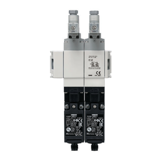
Series VP546/746(-XA###) modular
connection type
"###" represent numerical digits.
Note)
Safety component as defined by the Machinery
Directive 2006/42/EC article 2c/ The Supply of
Machinery (safety) Regulations 2008 part 2.4(2)(c).
The intended use of this valve is to vent a protected system to
atmosphere when it is de-energised. When properly integrated into a
suitable safety system the duplex valves are compatible for use in
systems up to Category 4, and the single valves are compatible for use
in systems up to Category 2 as defined by EN ISO 13849-1.
1 Safety Instructions
These safety instructions are intended to prevent hazardous situations
and/or equipment damage. These instructions indicate the level of
potential hazard with the labels of "Caution," "Warning" or "Danger."
They are all important notes for safety and must be followed in addition
to International Standards (ISO/IEC)
*1)
, and other safety regulations.
1)
ISO 4414: Pneumatic fluid power - General rules and safety requirements
for systems and their components
ISO 4413: Hydraulic fluid power - General rules and safety requirements
for systems and their components
IEC 60204-1: Safety of machinery - Electrical equipment of machines.
Part 1: General requirements
ISO 10218-1: Robots and robotic devices - Safety requirements for
industrial robots - Part 1: Robots
• Refer to product catalogue, Operation Manual and Handling
Precautions for SMC Products for additional information.
• Keep this manual in a safe place for future reference.
Danger indicates a hazard with a high level of risk which, if
Danger
not avoided, will result in death or serious injury.
Warning indicates a hazard with a medium level of risk
Warning
which, if not avoided, could result in death or serious injury.
Caution indicates a hazard with a low level of risk which, if
Caution
not avoided, could result in minor or moderate injury.
Warning
• Always ensure compliance with relevant safety laws and
standards.
• All work must be carried out in a safe manner by a qualified person in
compliance with applicable national regulations.
Caution
• The product is provided for use in manufacturing industries only. This
product must not be used in residential areas.
2 Specifications
Warning
• Special products (-XA###) might have specifications different from
those shown in this Instruction Manual. Contact SMC for specific
drawings.
2 Specifications - continued
2.1 Functional description
The product consists of either one or two solenoid operated 2 position 3
port valves, which are connected to a main air supply (in some cases via
an integrated soft-start valve). The valves are capable of performing the
safety function described in this document. The soft start valve is
intended to allow the end user to perform machine operational start up
procedures with reduced flow potential until a pre-set operational
pressure is achieved. At the defined pressure the soft start valve allows
full flow in order to achieve full operation. The soft start function is
intended for machine operation purposes and not for the performance of
a safety function.
2.2 Valve specifications
Standard
High pressure
Size
VP546
VP746
VP546K
Type of Actuation
Normally closed
Return method
Spring return
Fluid
Air
Proof pressure [MPa]
1.05
1.5
Internal pilot operating pressure
0.25 to 0.7
0.25 to 1
range [MPa]
External
S, D
0.05 to 0.7
0.05 to 1
Main
type
pilot
operating
pressure
SS, DS
0.25 to 0.7
0.25 to 1
pressure
type
range [MPa]
Pilot pressure
Same as main pressure (min. 0.25)
Ambient and operating fluid
-10~50 (no freezing / no condensation)
temperature [°C]
Ambient humidity
20 to 90% RH (no condensation)
Note 1)
Lubrication
Not required
Operating frequency: Max
30 cycles per minute
Operating frequency: Min
1 cycle per week
Note 2)
Duty cycle
Contact SMC
Response time
See 2.11.2
Note
Impact / Vibration resistance
150 / 30
Note 4, 5)
3)
[m/s²]
5 μm filtration or smaller
Air quality
Environment
Indoor use only
Enclosure (based on IEC60529)
IP65
Note 6)
B
[cycles]
10,000,000
5,000,000
10D
Maximum 20 years or
Maximum 20 years or when
when the number of cycles
Mission time [years or cycles]
the number of cycles = B
= B
, whichever occurs
10D
whichever occurs first
Note 7)
first
M-S type
0.5
0.8
0.5
Mass
M-D type
0.8
1.4
0.8
(examples)
M-SS type
0.7
1.3
0.7
[kg]
1.0
1.9
1.0
M-DS type
Table 1.
Note 1) If lubrication is used in the system, use class 1 turbine oil (no additive), ISO
VG32.
Note 2) The valve must be energised/de-energised at least once per week.
Note 3) See section 2.5 for switch impact/vibration specifications.
Note 4) Impact resistance:
• No malfunction resulted from the impact test using a drop impact tester.
• The test was performed in both energised and de-energised states to
the axis of and at right angles to the direction of the main valve and
armature (Values quoted are for a new valve).
Note 5) Vibration resistance:
• No malfunction occurred in a one-sweep test between 5 and 2000 Hz.
• Test was performed in both energised and de-energised states to the
axis of and at right angles to the direction of the main valve and armature
(Values quoted are for a new valve).
Note 6) The B
figure is estimated from SMC life tests under SMC test conditions.
10D
Note 7) See section 2.11.4 for details.
2.3 Flow characteristics
Note 1, 2)
VP546
S type
D type
SS type
Flow
Passage:
1→2
2→3
1→2
2→3
1→2
2→3
1→2
characteristics
(P→A)
(A→R)
(P→A)
(A→R)
(P→A)
(A→R)
(P→A)
C[liter/(s.bar)]
8.8
8.3
6.6
8.3
6.6
8.3
5.6
b
0.18
0.18
0.13
0.18
0.13
0.18
0.06
Cv
2.1
2.0
1.5
2.0
1.5
2.0
1.3
Table 2.
2 Specifications - continued
VP746
S type
D type
Flow
Passage:
1→2
2→3
1→2
2→3
characteristics
(P→A)
(A→R)
(P→A)
(A→R)
C[liter/(s.bar)]
14.2
12.3
10.8
12.3
b
0.22
0.25
0.13
0.25
Cv
3.4
3.0
2.5
3.0
Table 3.
Note 1) Flow characteristics shown are for standard pressure type and high
pressure type.
Note 2) For flow during soft start mode, see section 2.8.2.
The flow direction is identifiable by an arrow in the manifold itself. Please
see some examples in Figure 1.
VP746K
Figure 1.
2.4 Pilot valve specifications
Electrical entry
D or Y type DIN terminal (See 3.8.1)
Coil rated voltage [VDC]
Allowable voltage fluctuation
Power consumption [W]
Surge voltage suppressor
Indicator light
Table 4.
Note 1) Valve state is not defined if electrical input is outside of specified operating
ranges.
2.5 Limit switch specifications
Note 6)
Omron
G1/2 conduit
Electrical entry
M12 connector
,
10D
Contact resistance [mΩ]
25 max
Note 7)
5 VDC 1mA
Minimum permissible load
0.8
(resistive load)
1.4
Rated voltage [VDC]
1.3
Maximum permitted load current [mA]
1.9
Maximum permitted load inductance [H]
Rated insulation voltage [V]
Electric shock protection class
Pollution degree
Vibration / Impact resistance
Table 5.
Note 1) For the purposes of EN ISO 13849-2 table D.2 the switch is de-rated from
the figures specified by the switch manufacturer. The switch load must be
limited in the application in order to maintain the specified safety
performance, including the B
and mission time.
10D
Note 2) The Omron switch is subject to the following vibration and impact limitations
specified by the manufacturer:
• 'Contact opening time should be less than a 1 ms pulse under vibration
of 0.75 mm single amplitude, 10 to 55 Hz, 10 cycles in each direction for
45 minutes.'
• Impact: 300 m/s
2
(Contact open time: 1 ms maximum pulse).
Note 3) The Rockwell Automation switch is subject to the following vibration and
impact limitations specified by the manufacturer:
• Impact: IEC60068-2-7 (30gn (300m/s
• Vibration: IEC60068-2-6 (10...55Hz, 0.35mm amplitude).
2.6 Safety specification
DS type
• Safety function: When the valve is de-energised, the protected circuit
2→3
is vented to atmosphere.
(A→R)
• The valve assembly is compatible for use in systems up to either
8.3
Category 2 or Category 4 depending on configuration according to the
0.18
Safety Standard when integrated into a suitable safety system.
2.0
• In this section, 'the Safety Standard' refers to EN ISO 13849-1 and 'the
Validation Safety Standard' refers to EN ISO 13849-2 as referenced in
the Declaration of Conformity.
• Information about compatibility with the Safety Standard is given in
section 2.11.
2 Specifications - continued
SS type
DS type
2.7 Pneumatic symbols (examples)
1→2
2→3
1→2
2→3
2.7.1 S type
(P→A)
(A→R)
(P→A)
(A→R)
10.6
12.3
8.9
12.3
0.11
0.25
0.08
0.25
2.4
3.0
2.0
3.0
Figure 2. Internal pilot
(Omron switch variant shown for reference)
2.7.2 D type
24
Note 1)
-10% to +10%
0.45 per solenoid
Varistor
Figure 4. Internal pilot (Omron switch variant shown for reference)
LED
Rockwell Automation
M12 connector
50 max
5 VDC 5mA
(resistive load)
24
Note 1)
50
Note 1)
0.5
300
600
Class II (EN 60947-5-1)
Level 3 (EN 60947-5-1)
2, 3)
See note
Figure 5. External pilot (Omron switch variant shown for reference)
2.7.3 SS type
2
)), 3 pulses per axis).
Figure 6. Internal pilot (Rockwell switch variant shown for reference)
Figure 3. External pilot
Advertisement

Subscribe to Our Youtube Channel
Related Manuals for SMC Networks VP546 Series


Summary of Contents for SMC Networks VP546 Series
- Page 1 VP500-TF2Z537EN-A 2 Specifications - continued 2 Specifications - continued 2 Specifications - continued ORIGINAL INSTRUCTIONS 2.1 Functional description VP746 S type D type SS type DS type 2.7 Pneumatic symbols (examples) Flow Passage: 1→2 2→3 1→2 2→3 1→2 2→3 1→2 2→3 The product consists of either one or two solenoid operated 2 position 3 2.7.1 S type...
- Page 2 VP500-TF2Z537EN-A 2 Specifications - continued 2 Specifications - continued 2 Specifications - continued 2 Specifications - continued 2.9 Declaration of conformity Figure 7. External pilot (Rockwell switch variant shown for reference) Inlet pressure MPa P1 2.7.4 DS type Figure 10. Switching pressure (Close → Open) of soft start-up valve V2 2.8.2 Soft start flow The adjustable flow restriction is set by V1, see Figure 11 and 12.
- Page 3 VP500-TF2Z537EN-A 2 Specifications - continued 2 Specifications - continued 3 Installation - continued 3 Installation - continued • The valve response time OFF (T2) depends on the volume (V) and the The duplex valve has 2 channels made of identical valves. The use of Port Connection thread Tightening...
- Page 4 VP500-TF2Z537EN-A 3 Installation - continued 3 Installation - continued 3 Installation - continued 6 Maintenance • Use LAPP connectors together with seal packing (JPK-16, GP-13.5, 6.1 General maintenance 3.8.1.4 Using DIN connector with the pilot valve GPM20, or GPM12), and tighten to the specified tightening torque. Caution Caution Seal packing is sold separately.
-
Page 5: Troubleshooting Guide
VP500-TF2Z537EN-A 6 Maintenance - continued 7 Limitations of Use - continued • Class A equipment is equipment suitable for use in all locations other 6.5 Troubleshooting guide than those allocated in residential environments and those directly Symptom Possible fault Action connected to a low voltage power supply network which supplies Check pilot solenoid buildings used for domestic purposes.
Need help?
Do you have a question about the VP546 Series and is the answer not in the manual?
Questions and answers