Table of Contents
Advertisement
Quick Links
VS7-6-TF2Z554EN
ORIGINAL INSTRUCTIONS
Instruction Manual
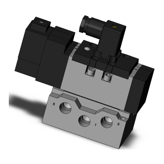
ISO 5599-1 Solenoid Valve - Metal Seal
Series VS7-6/8 Series
The intended use of this product is to control the movement of an
actuator.
1 Safety Instructions
These safety instructions are intended to prevent hazardous situations
and/or equipment damage. These instructions indicate the level of
potential hazard with the labels of "Caution," "Warning" or "Danger."
They are all important notes for safety and must be followed in addition
*1)
to International Standards (ISO/IEC)
, and other safety regulations.
*1)
ISO 4414: Pneumatic fluid power - General rules relating to systems.
ISO 4413: Hydraulic fluid power - General rules relating to systems.
IEC 60204-1: Safety of machinery - Electrical equipment of machines.
(Part 1: General requirements)
ISO 10218-1: Robots and robotic devices - Safety requirements for
industrial robots - Part 1: Robots.
• Refer to product catalogue, Operation Manual and Handling
Precautions for SMC Products for additional information.
• Keep this manual in a safe place for future reference.
Caution indicates a hazard with a low level of risk which, if
Caution
not avoided, could result in minor or moderate injury.
Warning indicates a hazard with a medium level of risk
Warning
which, if not avoided, could result in death or serious injury.
Danger indicates a hazard with a high level of risk which, if
Danger
not avoided, will result in death or serious injury.
Warning
• Always ensure compliance with relevant safety laws and
standards.
• All work must be carried out in a safe manner by a qualified person in
compliance with applicable national regulations.
• If this equipment is used in a manner not specified by the
manufacturer, the protection provided by the equipment may be
impaired.
Caution
• The product is provided for use in manufacturing industries only. Do
not use in residential premises.
2 Specifications
2.1 Valve specifications
Model
VS7-6
VS7-8
Fluid
Air / Inert gas
Operating pressure range [MPa]
0.1 to 1.0
Ambient and fluid temperature [°C]
5 to 60
Flow characteristics
Refer to catalogue
Response time
Duty cycle
Contact SMC
Minimum operating frequency
1 cycle / 30 days
Maximum operating
2 position
20
frequency [Hz]
3 position
Note 1)
10
Manual override
Non-locking type, Locking type
Lubrication
Not required
Impact / vibration resistance [m/s
2
]
Note 2)
150 / 50
Enclosure (based on IEC60529)
IP65
Note 3)
Mounting orientation
Unrestricted
2 Specifications - continued
Applicable sub-plate
2 position single
2 position double
3 position closed center
Weight [kg]
Note 4)
3 position exhaust center
3 position pressure center
3 position double pilot check
Table 1.
Note 1) Maximum operating frequency for 3 position double pilot check valve is 8Hz.
Note 2) Impact resistance: No malfunction resulted during the impact test using a
drop impact tester. The test was performed one time each in the axial and
right angle directions of the main valve and armature for both energized
and de-energized conditions. (Values quoted are for a new valve)
Vibration resistance: No malfunction resulted during a one-sweep test
between 8.3 and 2000 Hz. The test was performed in the axial and right
angle directions of the main valve and armature for both energized and de-
energized conditions. (Values quoted are for a new valve).
Note 3) If there is vibration or impact, install the valve so that the spool is
perpendicular to the direction of vibration.
If there is no vibration or impact, install the spool valve so that it is
horizontal.
Note 4) Weight is without sub-plate. Sub-plate weight: 0.37 kg.
2.2 Solenoid specifications
Coil rated
DC
voltage [V]
AC [50/60 Hz]
Electrical entry
Coil insulation class
Allowable voltage fluctuation
24 VDC
Current [A]
Inrush/holding
12 VDC
50 Hz
Inrush
60 Hz
100 VAC
50 Hz
Holding
60 Hz
Current [A]
50 Hz
Inrush
60 Hz
200 VAC
50 Hz
Holding
60 Hz
Surge voltage suppressor
AC
Indicator light
DC
Table 2.
2.3 Manifold specifications
Manifold block size
ISO size 1
Valve series
VS7-6
Note)
Valve stations
1 to 10 stations
1/4", 3/8", C6, C8, C10
A,B port
Piping
1/4", 3/8", C12
P, R1, R2 port
Table 3.
Note) Stations including F.R. unit (equivalent to 2 stations).
2.4 Pneumatic symbol
Refer to catalogue for pneumatic symbol.
2.5 Indicator light
Indicator light
Figure 1.
2.6 Special products
Warning
Special products (-X) might have specifications different from those
15
shown in this section. Contact SMC for specific drawings.
10
3 Installation
VS7-1
VS7-2
3.1 Installation
0.460
0.655
0.560
0.74
• Do not install the product unless the safety instructions have been read
and understood.
0.635
0.89
3.2 Environment
0.990
2.12
• Do not use in an environment where corrosive gases, chemicals, salt
water or steam are present.
• Do not use in an explosive atmosphere.
• Do not expose to direct sunlight. Use a suitable protective cover.
• Do not install in a location subject to vibration or impact in excess of
the product's specifications.
• Do not mount in a location exposed to radiant heat that would result in
temperatures in excess of the product's specifications.
3.3 Piping
• Before connecting piping make sure to clean up chips, cutting oil, dust
etc.
• When installing piping or fittings, ensure sealant material does not
enter inside the port. When using seal tape, leave 1 thread exposed
on the end of the pipe/fitting.
12, 24
• Tighten fittings to the specified tightening torque.
100, 200
Thread (Rc)
DIN terminal
1/4
Class B equivalent
3/8
-15 to 10% of rated voltage
1/2
0.075
3/4
0.15
0.049
3.4 Lubrication
0.043
0.031
• SMC products have been lubricated for life at manufacture, and do not
0.020
require lubrication in service.
0.024
• If a lubricant is used in the system, refer to catalogue for details.
0.021
0.015
3.5 Air supply
0.010
• Use clean air. If the compressed air supply includes chemicals,
Varistor
synthetic materials (including organic solvents), salinity, corrosive gas
Neon
etc., it can lead to damage or malfunction.
LED
• Install an air filter upstream of the valve. Select an air filter with a
ISO size 2
filtration size of 5 μm or smaller.
VS7-8
3.6 Manual override
3/8", 1/2"
1/2", 3/4"
• Regardless of an electric signal for the valve, the manual override is
used for switching the main valve. Since connected equipment will
operate when the manual override is activated, confirm that conditions
are safe prior to activation.
• Locked manual overrides might prevent the valve responding to being
electrically de-energised or cause unexpected movement in the
equipment.
Indicator light
3.6.1 Non-locking push type
• Push on the manual override button (orange) using a small-bladed
screwdriver or suitable tool until the valve switches (ON position).
• Hold this position for the duration of the check (ON position).
• Release the button and the override will re-set to the OFF position.
3.6.2 Push-locking slotted type
3.6.2.1 To lock:
• Using a small-bladed screwdriver in the slot, push the manual override
button down until it stops.
3 Installation - continued
• Turn the override button 90° in the direction of the arrow until it stops
(ON position).
Warning
• Remove the screwdriver. The valve will remain switched ON.
Warning
In this position the manual override is in the locked 'ON' position.
3.6.2.2 To unlock:
Caution
• Place a small-bladed screwdriver in the slot, push down the manual
override button.
• Turn the override button 90° in the reverse direction of the arrow.
• Remove the screwdriver and the manual override will re-set to the OFF
position.
3.7 Mounting
Tightening torque [N·m]
8 to 12
• Ensure gaskets are in good condition, not deformed and are dust and
15 to 20
debris free.
20 to 25
• When mounting valves ensure gaskets are present, aligned and
28 to 30
securely in place and tighten screws to torque values as per table
Table 4.
below.
Series
Caution
VS7-6
VS7-8
3.8 Electrical circuit
Warning
• Surge suppression should be specified by using the appropriate part
number. If a valve type without suppression is used, suppression must
be provided by the host controller as close as possible to the valve.
Caution
Warning
Neon
light
Manual override
button
Figure 2.
Neon
light
Manual override
button
Figure 3.
Warning
Caution
Recommended tightening torque [N∙m]
Thread size
M5
2.3 to 3.7
M6
4 to 6
Table 5.
Caution
AC
DC
Single solenoid
With indicator light
Neon
light
LED
With indicator light / surge voltage suppressor
Neon
light
LED
Double solenoid, 3 position
With indicator light
Neon
light
LED
LED
With indicator light / surge voltage suppressor
LED
LED
Figure 4.
Page 1 of 2
Advertisement
Table of Contents

Subscribe to Our Youtube Channel
Related Manuals for SMC Networks VS7-6 Series


Summary of Contents for SMC Networks VS7-6 Series
- Page 1 VS7-6-TF2Z554EN 2 Specifications - continued 3 Installation 3 Installation - continued • Turn the override button 90° in the direction of the arrow until it stops ORIGINAL INSTRUCTIONS Applicable sub-plate VS7-1 VS7-2 3.1 Installation (ON position). 2 position single 0.460 0.655 Warning •...
- Page 2 VS7-6-TF2Z554EN 3 Installation - continued 6 Maintenance - continued 8 Product Disposal • Maintenance of pneumatic systems should be performed only by This product shall not be disposed of as municipal waste. Check your 3.9 Wiring qualified personnel. local regulations and guidelines to dispose this product correctly, in order Ground •...
Need help?
Do you have a question about the VS7-6 Series and is the answer not in the manual?
Questions and answers