Table of Contents
Advertisement
Quick Links
55-VPA-SMX85EN-A
ORIGINAL INSTRUCTIONS
Refer to Declaration of
Conformity for relevant
Instruction Manual
Directives
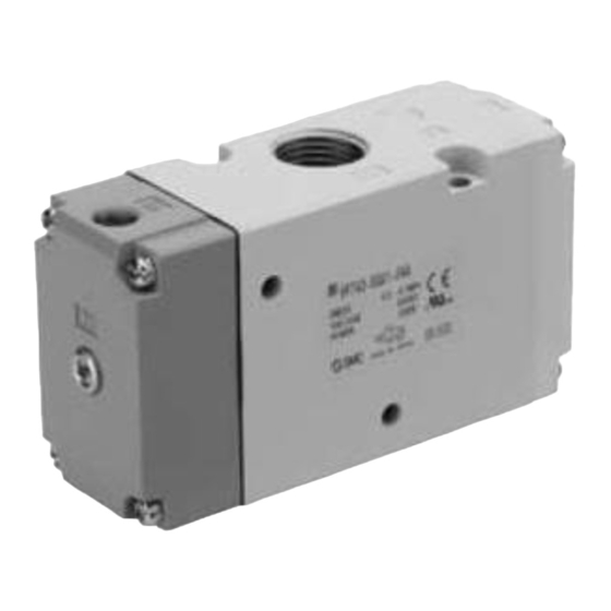
Air operated 3 port valves
55-VPA(-1) 300/500/700 Series
Symbol
-10°C ≤ Ta ≤ +50°C
ATEX classification: II 2 G Ex h IIB T6 Gb
II 2 D Ex h IIIB T70°C Db
Certificate reference: SMC 19.0052 X
For special conditions of use see section 1.2.
The intended use of this product is to provide directional control to
pneumatic actuators (or similar industrial pneumatic equipment).
1 Safety Instructions
1.1 General safety instructions
These safety instructions are intended to prevent hazardous situations
and/or equipment damage. These instructions indicate the level of
potential hazard with the labels of "Caution," "Warning" or "Danger."
They are all important notes for safety and must be followed in addition
*1)
to International Standards (ISO/IEC)
, and other safety regulations.
*1)
ISO 4414: Pneumatic fluid power - General rules relating to systems.
ISO 4413: Hydraulic fluid power - General rules relating to systems.
IEC 60204-1: Safety of machinery - Electrical equipment of machines.
(Part 1: General requirements)
ISO 10218-1: Manipulating industrial robots -Safety. etc.
• Refer to product catalogue, Operation Manual and Handling
Precautions for SMC Products for additional information.
• Keep this manual in a safe place for future reference.
Caution indicates a hazard with a low level of risk which, if
Caution
not avoided, could result in minor or moderate injury.
Warning indicates a hazard with a medium level of risk
Warning
which, if not avoided, could result in death or serious injury.
Danger indicates a hazard with a high level of risk which, if
Danger
not avoided, will result in death or serious injury.
Warning
• Always ensure compliance with relevant safety laws and
standards.
• All work must be carried out in a safe manner by a qualified person in
compliance with applicable national regulations.
1.2 Special conditions of use
Warning
• Protect from impacts using an ATEX compliant enclosure.
• To avoid the build-up of electrostatic charge, do not mount in areas
subject to electrostatic charging mechanisms and clean only with a
damp cloth and allow to dry naturally.
2 Specifications
2.1 Valve specifications
Fluid
Air
Type of actuation
N.C or N.O. (Convertible)
Standard
0.2 to 1.0
Operating pressure range (MPa)
For vacuum
-100 kPa to 0.2
0.2 to 1.0 (Equivalent to the
Pilot pressure (MPa)
operating pressure or more)
Maximum operating frequency (Hz)
1
Air filtration (µm)
5 (or less)
Ambient and fluid temperature (°C)
-10 to 50 (No freezing)
Lubrication
Not required
Mounting orientation
Unrestricted
Impact/Vibration resistance (m/s)
Note
300/50
1)
Note 1) Impact resistance: No malfunction to axis and right angle
directions of main valve, each one time when pilot signal ON and OFF
(Values at the initial period).
Vibration resistance: No malfunction from test with 45 to 2000
Hz one sweep, to axis and right angle direction of main valve, each one
time when pilot signal ON and OFF (Values at the initial period).
Note 2) For general specifications (materials, flow rate, dimensions,
weight) please refer to the catalogue for the standard VPA(-1) Series.
2.2 Production batch codes
Co nstructio n
P ro ductio n batch co des
Year / M o nth Jan Feb M ar A pr M ay Jun Jul A ug Sep Oct No v Dec
201 9
Xo
XP
XQ
XR
XS
XT XU
XV
XW XX
2020
yo
yP
yQ
yR
yS
yT
yU
yV
yW
yX
...
...
...
...
...
...
...
...
...
...
...
2024
Co
CP
CQ CR
CS
CT CU CV
CW CX
Note: The batch code is included on the product label.
3 Installation
3.1 General
Warning
• Do not install the product unless the safety instructions have been read
and understood.
• Protect from impacts using an ATEX compliant enclosure.
3.2 Vacuum type valves:
Caution
• When using vacuum type valves, please note that the Ex atmosphere
could be drawn into the pneumatic circuit via the pilot exhaust port
(breathing hole) of the valve. This port is threaded, allowing it to be
piped outside of the Ex zone if necessary. See fig.1 for location of
breathing hole (55-VPA3*-1 shown as an example).
Fig.1
3.3 Torque values for valves mounted on sub-base and manifold.
Caution
Valves are attached to the manifold/sub-base with 2 mounting screws.
Tighten the mounting screws to the appropriate tightening torque.
Valve
Tightening torque (Nm)
55-VPA3*-1
0.8
55-VPA5*-1
1.4
55-VPA7*-1
2.9
3 Installation (continued)
3.4 Environment
Warning
• Do not use in an environment where corrosive gases, chemicals, salt
water or steam are present.
• Do not expose to direct sunlight. Use a suitable protective cover.
• Do not install in a location subject to vibration or impact in excess of
the product's specifications.
• Do not mount in a location exposed to radiant heat that would result in
temperatures in excess of the product's specifications.
• Do not mount in areas subject to electrostatic charging mechanisms.
3.5 Piping
Warning
• When using the vacuum type valves, consideration must be given to
the piping of the pilot exhaust, see section 3.2 for details.
• The function of body ported valves can be changed by rotating the end
plate, see section 4.2 for details.
Caution
• Before connecting piping make sure to clean up chips, cutting oil, dust
etc.
• When installing piping or fittings, ensure sealant material does not
enter inside the port. When using seal tape, leave 1 thread exposed
on the end of the pipe/fitting.
• For details regarding pipe sizes, please refer to the catalogue for the
standard VPA(-1) Series.
• Tighten fittings to the specified tightening torque.
Xy
XZ
Note: For connection thread M5, first tighten by hand then use a suitable
yy
yZ
wrench to tighten the fitting an additional 1/6 to 1/4 turn. The reference
...
...
value for the tightening torque is 1 to 1.5 N•m.
Cy
CZ
3.6 Lubrication
Caution
• SMC products have been lubricated for life at manufacture, and do not
Connection thread size (R, NPT)
1/8
1/4
3/8
1/2
require lubrication in service.
• If a lubricant is used in the system, refer to the catalogue for the
standard VPA(-1) Series for information.
4 Settings
4.1 Change of Base Mount valve function
The function of base mount type valves can be switched between
normally closed (N.C.) and normally open (N.O.).
• Sub-base mounted
Example showing change from N.C. to N.O. See fig.2.
Remove the valve body from the sub-base and reset the "" mark on
the body corresponding to the "N.O." mark on the sub-base.
Then remove the end plate from the valve body and rotate it 180° so
that the "N.O." mark is at the top of the valve.
<N.C.>
Fig.2
Note: It is not necessary to remove the sub-base piping when
performing this change.
4 Settings (continued)
• Manifold mounted
When 55-VPA(-1) valves are mounted on a manifold the orientation of
the valve determines the function (NC or NO). Fig.3 shows valves A
and B configured as NC and valves C and D configured as NO.
Ports 2(A)
4.2 Change of Body port valve function
• The function (NO and NC) of the body ported valves is indicated by the
mark on the top of the end plate, see fig.4.
• To change the function from NC to NO, remove the end plate from the
body and rotate it 180° so that the NO mark is now at the top, see fig.5.
• Change the piping as shown below.
Tightening Torque (N•m)
Function
3 to 5
8 to 12
NC
15 to 20
20 to 25
NO
5 How to order
5.1 Valves
Body port:
55-VPA#42#-1-###-#(-X505)
Base mount:
55-VPA#44#-1-###
Please contact SMC for details.
5.2 Sub-plates and Manifolds.
Standard VP#00* sub-bases and VV3PA#* manifolds (including
blanking plates) are used for 55-VPA(-1) valves. Please refer to the
catalogue for the standard VPA(-1) Series.
6 Outline Dimensions
<N.O.>
The 55-VPA(-1) Series has the same dimensions as the standard VPA(-
1) Series please refer to the catalogue for the standard VPA(-1) Series.
7 Maintenance
7.1 General Maintenance
• Not following proper maintenance procedures could cause the product
to malfunction and lead to equipment damage.
• If handled improperly, compressed air can be dangerous.
Maintenance of pneumatic systems should be performed only by
qualified personnel.
• Before performing maintenance, turn off the power supply and be sure
to cut off the supply pressure. Confirm that the air is released to
atmosphere.
Valves C, D (NO)
Valves A, B (NC)
Manifold
Port 3(R)
Port 1(P)
Fig.3
End plate
mark (NC)
Fig.4
End plate
mark (NO)
Fig.5
Port
P
A
R
Supply
Output
Exhaust
Exhaust
Output
Supply
Caution
Page 1 of 2
Advertisement
Table of Contents

Related Manuals for SMC Networks 300 Series


Summary of Contents for SMC Networks 300 Series
- Page 1 55-VPA-SMX85EN-A 2 Specifications 3 Installation (continued) 4 Settings (continued) • Manifold mounted ORIGINAL INSTRUCTIONS 2.1 Valve specifications 3.4 Environment When 55-VPA(-1) valves are mounted on a manifold the orientation of Fluid Warning the valve determines the function (NC or NO). Fig.3 shows valves A Refer to Declaration of Type of actuation N.C or N.O.
- Page 2 55-VPA-SMX85EN-A 7 Maintenance (continued) • After installation and maintenance, apply operating pressure and power to the equipment and perform appropriate functional and leakage tests to make sure the equipment is installed correctly. • Do not make any modification to the product. •...
Need help?
Do you have a question about the 300 Series and is the answer not in the manual?
Questions and answers