Omron S8T-DCBU-01 Manual
Dc backup block for s8ts
Hide thumbs
Also See for S8T-DCBU-01:
- Brochure & specs (6 pages) ,
- Manual (18 pages) ,
- Manual (16 pages)
Advertisement
Quick Links
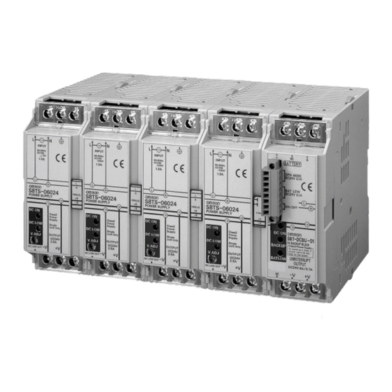
DC Backup Block for S8TS
S8T-DCBU-01
DC Backup Block for S8TS
for Preventing 24 VDC Outages due to
Instantaneous Power Failures
• Supplies 24 VDC for a fixed period of time even during
AC input outages to considerably improve system reliability.
• Block Power Supply Basic Block is connected by the Bus Line
Connector.
Simple system configuration
• Alarms are notified by indication on main unit and by alarm
signal output.
Ordering Information
DC Backup Block
(See Note 1.)
Input voltage
24 to 28 VDC
Note: 1. One Bus Line Connector, S8T-BUS03, is included as an accessory.
2. When specified battery, LC-@122R2@@, is in use: Max. 3.7 A
When specified battery, LC-@123R4@@, is in use: The output current can be selected by the overcurrent protection operating point
selector.
Battery Holder
Model number
S82Y-TS01
Basic Block
Type
Screw terminal type
With Bus Line Connectors
Without Bus Line Connectors
Connector terminal type With Bus Line Connectors
Without Bus Line Connectors
Note: Use S8T-DCBU-01 together with the Block Power Supply Basic Block(s).
For more information on the Basic Block, refer to the S8TS data sheet (Cat.No. T022-E1).
Battery
See on Page 2 for the battery ordering infomation.
Output voltage
24 V
Input voltage
100 to 240 VAC
Block Power Supply Basic Block
Output current
3.7 A/ 8 A (See note 2.)
Output voltage/Output current
24 V/ 2.5 A
DC Backup Block for S8TS
DC Backup Block
Model number
S8T-DCBU-01
Model number
S8TS-06024-E1
S8TS-06024
S8TS-06024F-E1
S8TS-06024F
S8T-DCBU-01
L-39
Advertisement

Related Manuals for Omron S8T-DCBU-01


Summary of Contents for Omron S8T-DCBU-01
- Page 1 S8TS-06024F-E1 Without Bus Line Connectors S8TS-06024F Note: Use S8T-DCBU-01 together with the Block Power Supply Basic Block(s). For more information on the Basic Block, refer to the S8TS data sheet (Cat.No. T022-E1). Battery See on Page 2 for the battery ordering infomation.
- Page 2 Note: 1. The designated battery is made by Matsushita (Panasonic). 2. The designated battery is rated at 12 V. Use two batteries in series. 3. S8T-DCBU-01 shall be connected with S8TS-06024@ when in use. 4. Consult OMRON or Panasonic sales representatives when purchasing batteries.
- Page 3 S8TS-06024@ to be connected to the S8T-DCBU-01 shall be one. • Connect S8T-DCBU-01 to S82Y-TS01 having its fuse replaced with an UL-Listed and DC rated 32 VDC min./ 3 A max. one. • Connect an UL-Listed and DC rated 32 VDC min./ 2.5 A max. fuse at the location shown in Figure 1.
-
Page 4: S8T-Dcbu-01
Notes 2, 4 and 8.) (S82Y-TS01) be used. If the S82Y-TS01 is not used, insert a switch and a fuse between the battery and the S8T-DCBU-01. For selection Table 1. Possibility of Overdischarge due to Standby and layout of the switch and fuse, refer to Battery Holder S82Y-TS01 Current Consumption on page 44. - Page 5 0.11 A 0.5 months 0.25 months The battery self-discharges even when it is disconnected from the S8T-DCBU-01. When transporting or storing the unit for long 2.2 A 1.0 month 0.5 months hours, charge the battery at the intervals specified below to pre- LC-@123 20 °C...
- Page 6 Relay (OPN MODE) (DC ON: Green) (1)-(2): ON LED lit Connect S8T-DCBU-01 and the battery using a cable having a wire (BACKUP: Red) diameter specified in Recommended Wire Diameter (page 55) within a wiring length of 1.5 m. Backup operation continues for about 7 seconds even after the out- put voltage of S8TS-06024@ is restored.
-
Page 7: Table Of Contents
Mounting and Removing the Bus Line Operation Check Connector After connecting S8TS-06024@ and S8T-DCBU-01, it is recom- mended to check the DC Backup Block if it is correctly operating in Pay attention to the following points to maintain electrical characteris- the following procedure. - Page 8 • Relay (BAT LOW) is in the LOW mode ((4)-(5): ON). Note: Battery discharge is continued by standby current consumption of the S8T-DCBU-01 even when backup operation is stopped. Do not leave the unit in this condition for a long time. (Refer to Battery Overdischarge on page 42.)
-
Page 9: Backup
Replace batteries pe- (1) Turn the AC power line OFF, and backup the S8T-DCBU-01. riodically to avoid the worst case. (2) Measure the time that the battery status output relay turns to 5. -
Page 10: Com
Periodic Inspection of the Battery • Check battery wiring and connections. (Check the batteries and S8T-DCBU-01 connections for loose screws.) We recommend periodically inspecting the battery as follows: • Make sure that backup operation is performed normally in a simu- lated power failure state. - Page 11 3. The peripheral temperature is specified at the place 50 mm downward from the main body of the DC Backup Block. 4. The operating temperature range of the battery is 0 to 40ºC; it is different from that of S8T-DCBU-01.
-
Page 12: Low
Note: Backup operation is not possible during the period (7 seconds (typical)) that the bat- Note: Backup operation is continued for seven seconds after the power is restored from a tery status output relay is LOW after the S8T-DCBU-01 is started up. power failure. - Page 13 • Ambient temperature: 25ºC • Battery: New product fully charged to 27.4 V • Length of wire between S8T-DCBU-01 and battery: 1.5 m 2. The backup time changes depend- ing on the capacity of connected equipment, ambient temperature, and battery service life.
- Page 14 1,000 (500) * * Values in parentheses are for the PFP-50N. Mounting Track (Material: Aluminum) PFP-100N2 35 ± 29.2 1,000 End Plate PFP-M M4 × 8 pan-head screw 35.5 35.3 11.5 M4 spring washer S8T-DCBU-01 L-52 DC Backup Block for S8TS...
- Page 15 EXPRESS OR IMPLIED, REGARDING NON-INFRINGE- MENT, MERCHANTABILITY OR FITNESS FOR PARTICU- In no event shall responsibility of Omron for any act exceed LAR PURPOSE OF THE PRODUCTS. ANY BUYER OR the individual price of the product on which liability is USER ACKNOWLEDGES THAT IT ALONE HAS DETER- asserted.
- Page 16 Shocks or vibrations may cause battery performance to may be disconnected due to vibration, causing electric shock. deteriorate. Do not connect the load or capacitor between S8T-DCBU-01 and [Maintenance] battery. This may shorten the battery service life or disable the...
- Page 17 Addi- tionally, install the end plate (PFP-M) to both ends of the power Connect the S8T-DCBU-01 to the right or left end of S8TS-06024@ supply. Basic Blocks.
- Page 18 ■ Troubleshooting This page lists the errors that may occur when the S8T-DCBU-01 is used, along with their probable causes and remedies. Check the relevant item. When Probable cause Description Remedies Installation S8T-DCBU-01 cannot be The Bus Line Connector is provided with a Set the selector on the Bus Line Connector connected.
- Page 19 Battery Overdischarge charged over 24 hours. current of the S8T-DCBU-01 while the AC on page 42 from now on. power is OFF. When inspecting Backup time is too short.
- Page 20 ALL DIMENSIONS SHOWN ARE IN MILLIMETERS. To convert millimeters into inches, multiply by 0.03937. To convert grams into ounces, multiply by 0.03527. In the interest of product improvement, specifications are subject to change without notice. Cat. No. T027-E1-02 S8T-DCBU-01 L-58 DC Backup Block for S8TS...
Need help?
Do you have a question about the S8T-DCBU-01 and is the answer not in the manual?
Questions and answers