Table of Contents
Advertisement
Advertisement
Table of Contents

Subscribe to Our Youtube Channel
Related Manuals for SEW-Eurodrive BST Series


Summary of Contents for SEW-Eurodrive BST Series
- Page 1 Drive Technology \ Drive Automation \ System Integration \ Services Operating Instructions Safety-Related BST Brake Module for Control Cabinet Installation Edition 10/2011 19357214 / EN Buy: www.ValinOnline.com | Phone 844-385-3099 | Email: CustomerService@valin.com...
- Page 2 SEW-EURODRIVE—Driving the world Buy: www.ValinOnline.com | Phone 844-385-3099 | Email: CustomerService@valin.com...
-
Page 3: Table Of Contents
Contents Contents General Information .................... 5 How to use this documentation ..............5 Structure of the safety notes ............... 5 1.2.1 Meaning of the signal words ............5 1.2.2 Structure of the section-related safety notes ....... 5 1.2.3 Structure of the embedded safety notes........5 Right to claim under warranty .............. - Page 4 Contents Installation ......................21 Mechanical Installation................21 6.1.1 Support rail mounting..............21 Electrical Installation ................. 23 6.2.1 Information on electrical installation........... 23 6.2.2 Double-pole safe disconnection..........24 6.2.3 Single-pole safe disconnection ..........25 Startup........................ 26 Operating states..................26 7.1.1 Brake module control under normal operating conditions, e.g. automatic operation of the plant ..........
-
Page 5: General Information
General Information How to use this documentation General Information Safety-Rated BST Brake Module How to use this documentation The documentation is part of the product and contains important information. The documentation is for everyone who works with this product. The documentation must be accessible and legible. Make sure that persons responsible for the system and its operation, as well as persons who work independently with the software and the connected units from SEW-EURODRIVE, have read through the doc- umentation carefully and understood it. -
Page 6: Right To Claim Under Warranty
General Information Right to claim under warranty Right to claim under warranty A requirement of fault-free operation and fulfillment of any rights to claim under limited warranty is that you adhere to the information in the documentation at hand. Therefore, read the documentation before you start working with the software and the connected units from SEW-EURODRIVE. -
Page 7: Safety Notes
Safety Notes Preliminary information Safety Notes The following basic safety notes must be read carefully to prevent injury to persons and damage to property. The operator must ensure that the basic safety notes are read and adhered to. Make sure that persons responsible for the plant and its operation, as well as persons who work independently on the unit, have read through the operating instruc- tions carefully and understood them. -
Page 8: Target Group
Safety Notes Target group Target group Only qualified personnel is allowed to perform installation, startup, fault repair and servicing (observe IEC 60364 or CENELEC HD 384 or DIN VDE 0100 and IEC 60664 or DIN VDE 0110 as well as national accident prevention guidelines). Qualified electricians in the context of these basic safety notes are persons familiar with installation, assembly, startup and operation of the product who possess the required qualifications. -
Page 9: Startup/Operation
Safety Notes Startup/operation Startup/operation • When the safety-related control voltage V / functional control voltage V 24 V safe 24 V in is disconnected, the DC link voltage V is still present at the brake module. DC link • The safety concept is only suitable for performing mechanical work on the system/ machine components. -
Page 10: Integrated Safety Technology
Integrated Safety Technology Safe condition Integrated Safety Technology The safety technology of the safety-related BST brake module described in this docu- ment has been developed and tested in accordance with the following safety require- ments: • Category 3 according to EN 954-1 •... -
Page 11: Block Diagram Bst
Integrated Safety Technology Safety function 3.2.1 Block diagram BST 9007201124185483 DC link voltage input V (terminal 1/2) DC link Brake output (terminals 13/14/15) Functional control voltage input V (terminal 3/4) 24 V in Safety-related control voltage input V (terminal 5/6) 24 V safe Safety function The following drive-related safety function can be used:... -
Page 12: Restrictions
Integrated Safety Technology Restrictions Restrictions WARNING Voltage is still present at the DC link connection of the frequency inverter even when disconnecting the safety-related control voltage V / functional control voltage 24 V safe 24 V in Severe or fatal injuries from electric shock. •... -
Page 13: Safety-Relevant Conditions
Safety-Relevant Conditions Permitted unit combinations Safety-Relevant Conditions The safety function of BST can only be used for safe operation of the system/machine if it is integrated correctly in an application-specific, higher-level safety function or safety system. It is essential that the system/machine manufacturer conducts a system/ machine-specific risk assessment (e.g. -
Page 14: Requirements On The Installation
Safety-Relevant Conditions Requirements on the installation Only SEW disk brakes may be connected to the BST module. Asynchronous motor type Brake DR.71 DR.80 DR.90 DR.100 DR.112 DR.132 DR.160 DR.180 DR.200 DR.225 type BE05 BE11 BE20 BE30 BE32 1) Brakes of the type BM or BM(G) 05 – 30 can be combined. Synchronous motor type Brake CMP.71... - Page 15 Safety-Relevant Conditions Requirements on the installation • You have to make sure that there is no transient coupling to the safety-related control voltage V 24 V safe • Observe the values specified for safety components when designing the safety circuits. •...
-
Page 16: Requirements On External Safety Controller
Safety-Relevant Conditions Requirements on external safety controller Requirements on external safety controller A safety relay can be used as an alternative to a safety controller. The following require- ments apply analogously. • The safety controller and all other safety-related subsystems must be approved for at least that safety class which is required in the overall system for the application- related safety function. -
Page 17: Sample Circuit For A "Safety Switching Device
Safety-Relevant Conditions Requirements on startup 4.3.1 Sample circuit for a "safety switching device" The following figure shows the basic connection of an external safety switching device (according to the before mentioned requirements). Observe the information in the respective manufacturer's data sheets for connection. Approved emergency stop device Safety switching device... -
Page 18: Requirements On The Operation
Safety-Relevant Conditions Requirements on the operation Requirements on the operation • Operation is only allowed within the limits specified in the data sheets. This applies to both the external safety relay as well as the BST. • You must check the safety functions on a regular basis to ensure proper functioning. The the test intervals should be specified in accordance with the risk assessment. -
Page 19: Unit Design
Unit Design Nameplate, type designation Unit Design Nameplate, type designation 5.1.1 Example: Type designation The following characteristic unit data can be read from the type designation: BST 0.6 S - 460V - 00 Version/type 460 V = AC 460 V (DC 190 V) Brake 400 V = AC 400 V (DC 167 V) voltage... -
Page 20: Scope Of Delivery Of Bst
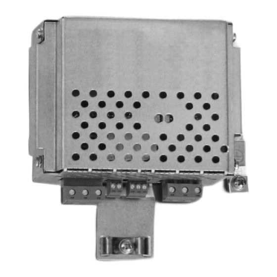
Unit Design Scope of delivery of BST Scope of delivery of BST The scope of delivery includes: • 1 safety-related BST brake module with installed holding fixture for support rail mounting • 4 attached plug connectors for terminal connections Safety-related BST brake module The following figure shows the unit design of BST x.xS-xxxV-00: [1] [2] [4] [5]... -
Page 21: Installation
Installation Mechanical Installation Installation Mechanical Installation 6.1.1 Support rail mounting The BST module is mounted onto a support rail in the control cabinet. 137090187 Mounting 1887424139 Safety-related BST brake module Support rail Upper holding fixture of the BST Notch, lower holding fixture of the BST Upper support rail edge Lower support rail edge 1. - Page 22 Installation Mechanical Installation 1. Press onto the BST from the top. This causes the lower support rail edge [6] to come Removal off the notch [4]. At the same time, remove the BST from the lower holding fixture. 2. You can remove the BST from the support rail once the lower lock unfastens. •...
-
Page 23: Electrical Installation
Installation Electrical Installation Electrical Installation INFORMATION • The safety-related BST brake module cannot be operated with sine-shaped power regeneration. • All poles must be disconnected from the supply system when work is carried out on the electrical section of the system. Dangerous voltages may still be present for up to 10 minutes after disconnection from the power supply system. -
Page 24: Double-Pole Safe Disconnection
Installation Electrical Installation 6.2.2 Double-pole safe disconnection The following figure shows the wiring inside the installation space: Installation space Safety switching device SVI24 Safety-related DC 24 V control voltage N.C. 24V safe S0V24 9007199388524427 The following figure shows the wiring outside the installation space: Installation space Outside Installation space... -
Page 25: Single-Pole Safe Disconnection
Installation Electrical Installation 6.2.3 Single-pole safe disconnection The following figure shows the wiring inside the installation space: Installation space Safety switching device SVI24 Safety-related control voltage DC 24 V N.C. 24V safe S0V24 9007199388553355 The following figure shows the wiring outside the installation space: Installation space Outside install. -
Page 26: Startup
Startup Operating states Startup Operating states • The brake is activated with the functional control voltage V when the DC link 24 V in voltage V and the safety-related control voltage V are present. DC link 24 V safe is present Brake released. -
Page 27: Brake Module Control Under Special Operating Conditions, E.g. Teach Or Jog Mode
Startup Operating states 7.1.2 Brake module control under special operating conditions, e.g. teach or jog mode For teach or jog mode, for example, timeouts shorter than 1 second are possible. After 20 control pulses, a timeout of minimum 3 min is mandatory in this case. Brake max. -
Page 28: Inspection/Maintenance
Inspection/Maintenance Inspection and maintenance intervals Inspection/Maintenance WARNING Risk of crushing if the hoist falls. Severe or fatal injuries. • Secure or lower hoist drives (danger of falling) • Isolate the inverter, the motor and the brake from the power supply before starting work, safeguarding them against accidental startup. -
Page 29: Service
Inspection/Maintenance Service Service Have the following information available when you require assistance from the SEW- EURODRIVE service: • Nameplate data (complete) • Type and extent of the problem • Time the problem occurred and any accompanying circumstances • Assumed cause Unit replacement Proceed as follows to replace a BST: •... -
Page 30: Applications
Applications Applications The following figures show the wiring diagrams for SBC with simultaneous STO (Safe Torque Off). INFORMATION • For safe single- and double-pole disconnection, refer to chapter "Electrical Instal- lation" • DC fuses F1/F2 are not required if the before mentioned requirements for the supply cable are met. -
Page 31: Disconnection Of Single Drives Via Inverter (Example Movidrive ® B)
Applications ® Disconnection of single drives via inverter (example MOVIDRIVE ® Disconnection of single drives via inverter (example MOVIDRIVE Higher-level controller DC 24 V Start Stop ® Emergency MOVIDRIVE B stop X13: DIØØ /Controller inhibit DIØ3 Enable/stop DCOM Reference potential binary signals X10: DGND Regerence potential binary signals... -
Page 32: Disconnection Of Single Drives Via Inverter And Dfs11B/21B Fieldbus Interface
Applications Disconnection of single drives via inverter and DFS11B/21B fieldbus inter- Disconnection of single drives via inverter and DFS11B/21B fieldbus interface Higher-level DC 24 V controller F_DI F_DO ® F_CPU MOVIDRIVE B X13: DIØØ /Controller inhibit DCOM Reference potential for binary signals DFS11B/21B X30: X31:... -
Page 33: Disconnection Of Group Drives
Applications Disconnection of group drives Disconnection of group drives Higher-level DC 24 V controller Start Stop Emergency stop ® MOVIDRIVE B Safety X13: relay DIØØ /Controller inhibit DIØ3 Enable/stop DCOM Reference potential binary signals X10: DGND Reference potential binary signals DBØØ... -
Page 34: Technical Data
Technical Data General technical data Technical Data 10.1 General technical data Brake module BST 1.2S-230V-00 BST 0.7S-400V-00 BST 0.6S-460V-00 1300 1337 1300 0772 0829 9714 Part number According to EN 61800-3 Interference immunity Interference emission with EMC- According to EN 61800-3 compliant installation IP20 Degree of protection... -
Page 35: Safety-Related Control Voltage
Technical Data Safety-related control voltage 10.2 Safety-related control voltage The following table shows the technical data for safety-related control voltage V 24 V safe at terminals 5/6: Safety-related control voltage V Min. Typical Max. 24 V safe DC 20.4 V DC 24 V DC 28.8 V Input voltage range... -
Page 36: 10.4 Dimension Drawing Of Bst In Control Cabinet Design
Technical Data Dimension drawing of BST in control cabinet design 10.4 Dimension drawing of BST in control cabinet design The following figure shows the dimension drawings of BST in control cabinet design: 9007199388556683 All dimensions in mm (in). Operating Instructions – Safety-Related BST Brake Module Buy: www.ValinOnline.com | Phone 844-385-3099 | Email: CustomerService@valin.com... -
Page 37: Address List
Index Index Applicable documentation ........6 Information on electrical installation Applications Brake cable (terminal 13/14/15)......23 Disconnection of group drives......33 Functional control cable (terminal 3/4)....23 Disconnection of single drives via inverter and Safety-related control cable (terminal 5/6)..23 DFS11B/21B fieldbus interface......32 Supply cable (terminal 1/2) ........23 ®... - Page 38 Index Startup ..............26 Startup requirements .........17 Safe condition ............10 Support rail mounting..........21 Safe disconnection Minimum clearance and mounting position ..22 double-pole ............24 Mounting BST onto a support rail ......21 single-pole............25 Removing BST from the support rail....22 Safety concept ............10 Safety control, external Requirements.............16 Safety notes .............7 Target group ............8...
Need help?
Do you have a question about the BST Series and is the answer not in the manual?
Questions and answers