Table of Contents
Advertisement
Quick Links
www.DataSheet4U.com
RGB Color Sensor
RGB Color Sensor Detects Subtle
Color Differences—Most Advanced
Color Sensor In the Industry
LED light source insures ease of
operation and long life
No separate light source is required
Remote control of color setting from PC
or PLC
4-color memory
4-output models available
3 models: lensed, precision fiber-optic,
versatile standard fiber-optic
IP66
Rugged die-cast metal housing
Ordering Information
RGB COLOR SENSOR
Type
Appearance
Lensed
Precision
fiber-optic
type
type
The shape of the
amplifier section is
amplifier section is
the same as for the
E3MC-(M)A
General-
purpose
ur ose
fiber-optic
type
ty e
Note:
Refer to the Specifications section of this data sheet.
Sensing distance
0
0
.
Standard sensing distance
E32-CC200
E32-T16
E32 T16
Spot
diameter
12 mm
50
100
60 ± 10 mm
(See Note.)
3 mm
50
100
20 ± 4 mm
(See Note.)
Varies with
the recom-
the recom-
mended
5 mm
(See Note 2.)
(See Note 2.) fiber.
fiber.
200 mm
E3MC
No. of
Output
Part number
outputs
1
NPN
E3MC-A11
PNP
E3MC-A41
4
NPN
E3MC-MA11
PNP
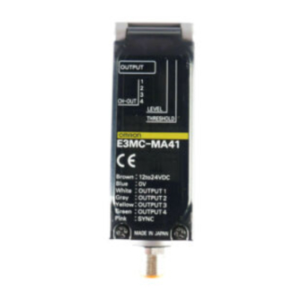
E3MC-MA41
1
NPN
E3MC-X11
PNP
E3MC-X41
4
NPN
E3MC-MX11
PNP
E3MC-MX41
1
NPN
E3MC-Y11
PNP
E3MC-Y41
4
NPN
E3MC-MY11
PNP
E3MC-MY41
Advertisement
Table of Contents

Related Manuals for Omron E3MC


Summary of Contents for Omron E3MC
- Page 1 RGB Color Sensor E3MC RGB Color Sensor Detects Subtle Color Differences—Most Advanced Color Sensor In the Industry LED light source insures ease of operation and long life No separate light source is required Remote control of color setting from PC...
-
Page 2: Specifications
Output Load current: 100 mA max. NPN open collector output with a maximum residual voltage of 1.2 V for the E3MC-(M)A11, E3MC-(M)X11, and E3MC-(M)Y11. PNP open collector output with a maximum residual voltage of 2.0 V for the E3MC-(M)A41, E3MC-(M)X41, and E3MC-(M)Y41. - Page 3 Fiber Head right. Item E3MC-(M)A E3MC-(M)X Color discrimination Mode C mode Response time Standard mode Tolerance (θ) 15° 10° Detectable colors 11 standard colors Sensing target Sensing target 3. 1-output models only: E3MC-A 4. 4-output models only: E3MC-MA /-MX /-MY...
-
Page 4: Application Examples
E3MC E3MC www.DataSheet4U.com Application Examples PATTERN POSITIONING DETECTING INTERNAL YELLOW RESIN PLATES OF A BATTERY DISCRIMINATING FRONT AND BACK DETECTING LABELS SIDES OF OBJECTS STANDARD SENSING OBJECTS Color Munsell color notation (See Note.) (11 standard colors) White N9.5 4.5/12.0 Yellow/red 6.0/11.5... -
Page 5: Engineering Data
Angle (°) GENERAL-PURPOSE FIBER-OPTIC TYPE Recommended Fiber: Diffuse Fiber-Optic The following optical fibers are recommended for use with the Note: 1. The E3MC-(M)Y discriminates eleven colors at the E3MC-(M)Y above distances. For a typical example, nine colors are discriminated at a sensing distance of 12 mm. - Page 6 AVAILABLE OPTICAL FIBERS In addition to the previous recommended optical fibers, the following optical fibers are available for the E3MC-(M)Y . Refer to the E3X-NH Datasheet (E258-E1) for the following optical fibers in detail. Optical fibers other than the following are not available.
- Page 7 E3MC E3MC E32-D11L Sensing Target: Red, Blue, and Yellow Films Sensing target: Blue/Green 38 x 38 mm -TC200 -T11L -T16 -T17L Distance X (mm) Distance X (mm) Sensing target: Film in Red (rosco/UX, scarlet) Sensing target: Film in Yellow (rosco/UX, straw) Sensing target: Film in Blue (rosco/UX, skyblue) The above color films are made by the rosco company.
- Page 8 C. Response Time Selection 3 ms (6 ms): The E3MC can stably detect minute differences of color. Set the response time to 3 ms for usual applications. 1 ms (2 ms): The E3MC will be in quick-response operation. Set the response time to 1 ms if high-speed response is required.
-
Page 9: Operation
E3MC E3MC Operation OUTPUT CIRCUITS Connector Pin Arrangement For All Models Note: Pin 8 is not used. E3MC- 11 with NPN Output (1-output Models) Brown Control output Load White Load Gray Not used/Answer-back output Yellow 12 to 24 VDC... - Page 10 E3MC E3MC www.DataSheet4U.com E3MC- 41 with PNP Output (1-output Models) Brown External synchronous input Pink Bank selection input 2/Not used Green Bank selection input 1/ Remote control input 12 to 24 VDC Yellow Note used/Answer back output Gray Control output...
- Page 11 When the E3MC is in conforming output mode, the control output of the E3MC will be ON if the detection level exceeds the threshold level and OFF if the detection level does not exceed the threshold level.
- Page 12 As the detected color becomes closer to the registered color, the number of illuminated detection level indicators increases. When the E3MC is in conforming output mode, the control output will be ON if the detection level exceeds the threshold level and OFF if the detection level does not exceed the threshold level.
-
Page 13: Technical Guide
TECHNICAL GUIDE If the E3MC does not detect metal or glossy objects accurately, change the mounting angle of the E3MC so that it will not receive regular reflection light directly reflected from the objects. The mounting angle of the E3MC-X can be adjusted to approximately 10°... - Page 14 Single-Output Models ONLY (E3MC-A /E3MC-X /E3MC-Y The E3MC in RUN mode offers bank selection with external inputs by combining bank selection input 1 (yellow) and input 2 (green). The selected bank is active when the indicator is illuminated. NPN (E3MC-A11/-X11/-Y11)
- Page 15 Checking Method will be an answer-back output for 0.3 s if the signal is correctly Mode A or B of the E3MC will be displayed for 3 s after mode received. setting. When the mode selector is set to TEACH, the mode can be checked from the operation indicator.
- Page 16 Function 3: Remote control of threshold adjustments The following is an example of ladder programming for setting through the PLC or PC control signals. Full control of the E3MC is possible using this function. Input either one of the following signals as remote control input.
- Page 17 E3MC E3MC Dimensions Unit: mm (inch) RGB COLOR SENSORS E3MC-A Mounting Dimension E3MC-MA 98 (3.85) 80 (3.14) Side Mounting Two, 5.5-dia holes 30.4 (1.19) Two, M2.6 x 6 Receiver (1.10) Four, M5 holes on both 60 (2.36) (1.53) (1.10) (1.18)
- Page 18 E3MC E3MC www.DataSheet4U.com Unit: mm (inch) E3MC-Y E3MC-MY Mounting Dimensions (Amplifier Unit) (3.86) (3.15) Side Mounting Two, 5.5-dia holes 30.4 Two, M2.6 x 6 (1.20) (1.10) Four, M5 holes on both (1.54) (1.10) (1.18) (0.31) sides (depth: 5.5) Receiver section...
- Page 19 E3MC E3MC E39-L114 DIN Rail Side-Mounting Brackets Mounting Holes (0.20) (0.87) (0.39) 2-R5 4-R2.6 (0.27) (0.27) (1.10) (0.43) E39-L115 DIN Rail Mounting Bracket DIN-rail...
-
Page 20: Installation
White Brown Green Yellow Pink Blue Connection Pin no. Wire color Purpose E3MC- E3MC- 11 or E3MC- 11 or E3MC- E3MC-M E3MC-M 11 or E3MC-M 11 or E3MC-M White Output Output 1 Brown Power supply (+V) Green Bank selection input 2... -
Page 21: Amplifier Unit
3-dia column 0.29 N m {3 kgf cm} max. the emitter. When using the E3MC-(M)Y , insert the fiber with E32-T16 0.49 N m {5 kgf cm} max. - Page 22 DIN-RAIL MOUNTING/REMOVAL WITH THE E39-L115 Mounting 1. Attach the E39-L115 Mounting Bracket to the E3MC with four 4. Press the E3MC in the direction indicated by arrow (3) and M5 screws. slide part A in the direction indicated by arrow (4) as shown...
- Page 23 Conformity/Non-conformity failure to detect the object. The light intensity may not be In the E3MC Color Sensor, term used to indicate when the reduced due to the “lens” effect of concentrating the light target color matches a reference color stored in the memory beam.
-
Page 24: Reference Information
• • Teach Function Red, green, blue, refers to the triple light source in the E3MC Circuitry in a sensor that allows sensor threshold to be set Color Sensor. By sensing the reflection level of each color, with the use of a “teach” input. Switching threshold is set the sensor can determine the exact color of the target. -
Page 25: Further Information
Power Up Ready • When connecting or disconnecting the cable, first remove the • The E3MC is ready to sense objects 100 ms after the unit is power to the E3MC. turned ON. • To avoid damage, tighten the metal connector securely by •... - Page 26 E3MC E3MC NOTE: DIMENSIONS SHOWN ARE IN MILLIMETERS. To convert millimeters to inches divide by 25.4. OMRON ELECTRONICS, INC. OMRON CANADA, INC. One East Commerce Drive 885 Milner Avenue Schaumburg, IL 60173 Scarborough, Ontario M1B 5V8 1-800-55-OMRON 416-286-6465 Cat. No. E256-E3-3 1/99 Specifications subject to change without notice.
Need help?
Do you have a question about the E3MC and is the answer not in the manual?
Questions and answers