Advertisement
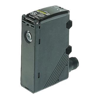
Mark Sensor
E3M-V
• Detects laminated or light-dispersing
objects in stable operation without be-
ing influenced by mirror reflection.
• Double indication of the detection level
and threshold level allows easy grasp
of the operating status and easy ad-
justment.
• Automatically sets to the optimum
threshold level while sensing objects
are being conveyed and incorporates
an auto-teaching function that discrim-
inates between the mark and back-
ground and turns ON when the mark is
detected.
• IP67 watertight construction with M12
rotary connector
• High response speed of 50 s and half
the size of OMRON's conventional
models.
Applications
Dependably Detects Marks on Laminated Sheets
The coaxial optical system ensures a long sensing distance and
stable sensing characteristics over a wide angle range, even for
objects that are distance-fluctuating or leaning at an angle, or for
laminated objects with marks, which conventional models have
difficulty in detecting
E3M-V
Auto-Teaching
An auto-teaching function automatically sets the threshold value
upon a Remote Control input while the workpiece is moving.
There is no need to position the mark at the optical spot.
A-133
Advertisement
Table of Contents

Related Manuals for Omron E3M-V


Summary of Contents for Omron E3M-V
- Page 1 Remote Control input while the workpiece is moving. objects that are distance-fluctuating or leaning at an angle, or for There is no need to position the mark at the optical spot. laminated objects with marks, which conventional models have...
-
Page 2: Ordering Information
E3M-VG26 10+3 mm 1 x 4 mm E3M-VG12 E3M-VG17 Pre-wired 4 x 1 mm E3M-VG22 E3M-VG27 Possible to switch between vertical or horizontal connection using the M12 rotary connector Mounting Brackets Shape Model Quantity Remarks E39-L131 E39-L132 For rear mounting... -
Page 3: Specifications
1,000 VAC, 50/60Hz, 1 min. Vibration resistance Destruction: 10 to 55 Hz, 1-mm double amplitude or 150 m/s2 for 2 hrs each in X, Y, and Z directions Shock resistance Destruction: 500 m/s2 3 times each in X, Y, and Z directions... -
Page 4: Engineering Data
Standard Sensing Object (Color vs. Munsell) Glossy Sensing Objects Japan Color Enterprises Standard Color Card 230 Incline the Sensor to detect glossy objects so that the Sensor will not 11 standard colors Munsell color notation be influenced by the mirror reflection of light and to ensure the stable White N9.5... -
Page 5: Operation
Nomenclature Threshold Indicators (Red) Operation Indicator (Orange) Displays the threshold level. Lit when the output is ON. Mode Selector Detection Level Indicators (Green) Selects the mode. Displays the detection level. SET Button UP/DOWN Selector Used for teaching and threshold Increases the threshold value when adjustments. - Page 6 If teaching is unsuccessful, restart from the above step 2. Note: Follow the above steps so that the output will be turned ON whenever the mark is detected. By taking the opposite steps, the output will be turned OFF whenever the mark is detected and turned ON whenever the base is detected.
- Page 7 (Teaching will be unsuccessful if there is no difference in incident between the mark and base.) 4. If the answer-back signal is ON, the whole teaching operation will be completed. The output will be turned ON whenever the mark (i.e., the color with shorter passing time) is detected.
- Page 8 TIM000, TIM001, and TIM002 set values The input of any of the signals listed in the following table into the re- mote control I/O terminal allows remote control of the E3M-V. When the signal is accepted, answer-back output will be turned ON for 0.3 s.
- Page 9 Dimensions Note: All units are in millimeters unless otherwise indicated. Mark Sensors Connector Models Eight detection level indicators Seven level threshold indicators Operation indicator M2.6 M2.6 nut 10-dia. lens Mounting Holes Optical axis Two, 4.5-dia. Two, M4 mounting holes M12 Connector 47.8...
- Page 10 Accessories (Order Separately) Mounting Brackets E39-L131 Two, 4.2 dia. 905+15 Material: Stainless steel (SUS304) E39-L132 4.2 dia. 905+15 Material: Stainless steel (SUS304) A-142 Standard Photoelectric Sensors...
-
Page 11: Installation
Brown pin No. White Blue Power supply Black Brown (+V) DC/AC Note: 1 . pin No. 2 is not used. Power supply 2 . For details, refer to the Sensor I/O Connectors Catalog Blue (0V) (X065) Black Output E3M-V A-143... -
Page 12: Correct Use
Do not pull cables with pulling forces exceeding 50N. ALL DIMENSIONS SHOWN ARE IN MILLIMETERS. To convert millimeters into inches, multiply by 0.03937. To convert grams into ounces, multiply by 0.03527. Cat. No. E280-E2-01A-X In the interest of product improvement, specifications are subject to change without notice.
Need help?
Do you have a question about the E3M-V and is the answer not in the manual?
Questions and answers