Advertisement
Color sensor (LED type)
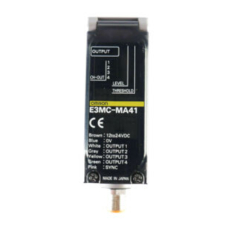
E3MC
Double Indication ensuring high
visibilty.
• Conformity with the registered colors can
be monitored at eight levels. (Detection
level indicators)
• Allows fine adjustment between fine or
rough discrimination while monitoring the
measured results. (Threshold level indica-
tors)
Stable and Powerful Detection for Inline Use
Stable detection is assured with a threshold
of ±10 mm for built-in amplifier type and
±4 mm for optical fiber type.
Fiber type and Stable detection
±4 mm.
Stable and Powerful Detection for Inline Use
Mounting is easy.
Long-distance Sensing with Built-in Amplifi-
er Type
Built-in amplifier type with a sensing distance of 60±10 mm is
available for a wide range of color discriminating applications.
Highly Resistant to Changes in Sensing Ob-
ject Brightness and Ambient Temperature.
• OMRON's unique Free Angle Optics (FAO: multi-layer po-
larized filter) is highly resistant to changes in the tint or
E3MC
RGB Color Sensor Discriminates Delicate
Differences in Color.
Features
60˚
10˚
10˚
brightness of sensing objects. Capable of discriminating
over 90 different colors.
• Wide temperature range from -20°C to 55°C and excellent
detection stability.
Maintenance-free LED Light Source
Incorporates RGB LED light sources with a long service life
more than several tens of thousand hours.
Great maintenance-cost saver ensuring high performance
(Halogen lamps used as light sources must be replaced or re-
adjusted every nine months or so.)
Principle of Detection
The E3MC detects colors by making use of the fact that the reflec-
tion ratio of a primary color (i.e. red, green or blue) reflected by an
object varies with the chromatically of the object. By using a high-
tech, multi-layer polarized filter called FAO (free angle optics), the
E3MC emits red, green and blue light on a single optical axis. The
E3MC receives the light reflected by the sensing objects through
the receiver and processes the red-green-blue ratio of the light to
discriminate the color of the sensing object.
FAO
(Blue: Reflected;
Red/Green: Passed)
FAO
(Green: Reflected; Red: Passed)
Red LED
(R)
Green LED
(G)
Blue LED
(B)
Monitor photodiode (see note)
Note: The monitor photodiode compensates LED output deviation that may be
caused by a temperature change. (Patent pending)
Photodiode
Receiver lens
R
G
B
B
G
R
Emitter lens
Time-sharing lighting
A-145
Advertisement
Table of Contents

Related Manuals for Omron E3MC


Summary of Contents for Omron E3MC
- Page 1 Stable and Powerful Detection for Inline Use The E3MC detects colors by making use of the fact that the reflec- tion ratio of a primary color (i.e. red, green or blue) reflected by an Stable detection is assured with a threshold object varies with the chromatically of the object.
- Page 2 IEC Standard and distribution in analog form. Different type discrimination IP66. You can use the E3MC without any problems in a wide can also be performed without bank restrictions by CPU pro- range of applications.
-
Page 3: Ordering Information
E3MC-MY41 200mm * Distance where 11 colors of standard sensing objects can be discriminated. As a typical example, 9 colors can be discriminated when 12 mm is set. Please contact us since the sensing distance should be defined. Analog output type... - Page 4 (1 output only) response time: 50 ms max. External synchronous input Response time: 1 ms max. (Note that the 4 output type cannot be used when the B mode is selected) Protective circuits Protection from load short-circuit and reversed power supply connection 1 output type: Standard mode: 3 ms max., high-speed mode: 1 ms max.
- Page 5 Accessories instruction manual *1. C mode, standard mode (response time), threshold: Distance range where 11 colors of standard sensing objects can be discriminated when = 15° (E3MC-(M) A##) or = 10° (E3MC-(M) X##) in the following figure in the standard mode.
- Page 6 Spot diameter 12 dia. 3-mm dia. Varies with the recommended fiber. Light source (wave length) Red LED (680 mm), green LED (525 mm), blue LED (450 mm) Power supply voltage 24 V DC ±10%, ripple (p-p) 10% or less Power consumption 100 mA max.
-
Page 7: Output Circuit Diagram
Blue CH3 CH2 CH1 Analog output type Connector Pin Arrangement Operation Brown indicator (orange) DC24V Yellow Calibration A Calibration B White Note: Pin 8 in not used. Main Pink Analog output circuit (red) Green Analog output (green) Gray Analog output... -
Page 8: Timing Chart
This status can be on hold by an output external synchronous input. It will be released by setting the This status can be on hold so that unwanted external synchronous input to OFF. color objects can be ignored while they are passing the sensing range. -
Page 9: Part Names/Functions
A Color Discrimination Mode Selection (Mode C is recommended for normal applications.) (6ms) Mode C: Color discrimination is performed according to R (red), G (green), and B (blue) ratio of the re- flection light even if the sensing objects fluctuate up and down within the rated sensing range. -
Page 10: Operation
3. Threshold Adjustment (If Required) Detection Level and Tolerance As the detected color becomes closer to the registered col- OUTPUT or (colors look alike), the number of lit detection level indi- cators (green) increase. The control output will turn ON if BLIP Sensor... - Page 11 As the detected color becomes closer to the registered color 3. Threshold Adjustment (If Required) (similar colors), the number of lit detection level indicators (green) increase. The control output will turn ON if the detec- tion level (green) exceeds the threshold level (red) and turn OUTPUT OFF if the detection level does not exceed the threshold level.
- Page 12 The measurement results will be directly output to the control output if the input from the external synchronous input terminal (pink) is set to OFF. The output will hold the previous status if the input of the external synchronous input terminal is set to ON. External synchronous input is valid in mode.
- Page 13 Remote teaching with manual input through a mechanical switch 0.3s 0.3s 0.3s Threshold 1 selected. Tolerance 1 Short-circuit the remote control input for 1.5 s or more to either of the follow- Tolerance 2 ing terminals according to the E3MC model. Tolerance 3 0.3s 0.6s 0.3s...
- Page 14 No. 4 terminal (yellow) to set the output values to 10 vious status since the outputs cannot be set to the same V. For the Y type, use the No. 1 terminal (white) to set them to 7 V. value.
- Page 15 Power Reset Time rate. This also applies to the through-beam type. E3MC is ready to sense an object in 100 ms after power-on. Bring the fiber head as close as pos- Therefore, use the devices connected to E3MC 100 ms after sible to the object and conduct power-on.
- Page 16 M3 screws • The bending radius of the fiber should be not less than the admissible bending radius given in Ratings/performance. • Do not bend the fiber within 20 mm from the head or ampli- fier coupling portion. 20 mm max.
- Page 17 Cutting Fiber • Insert a fiber into the Fiber Cutter and determine the length of the fiber to be cut. • Press down the Fiber Cutter in a single stroke to cut the fi- ber. View hole • The cutting holes cannot be used twice. If the same hole is used twice, the cutting face of the fiber will be rough and the sensing distance will be reduced.
- Page 18 Connection • Do not pull the Fiber Unit with force exceeding 9.8 N or press the Fiber Unit with force exceeding 29.4 N. The fiber is so thin that the utmost attention will be required to handle the fiber. • Do not bend the end of the Fiber Unit.
-
Page 19: Dimensions (Unit: Mm)
Dimensions (Unit: mm) Sensors E3MC-A## Mounting Dimensions E3MC-MA## Side Mounting E3MC-A81 Two, 5.5 dia. Two, M2.6 x 6 30.4 Receiver Four, M5 holes on both sides (depth: 5.5) Bottom Mounting Emitter Four, 5.5-dia. 16 ˚ holes 53.2 17.3 40.2 15.2 15.2... - Page 20 Mounting Brackets ALL DIMENSIONS SHOWN ARE IN MILLIMETERS. To convert millimeters into inches, multiply by 0.03937. To convert grams into ounces, multiply by 0.03527. Cat. No. E256-E2-04A-X In the interest of product improvement, specifications are subject to change without notice.
Need help?
Do you have a question about the E3MC and is the answer not in the manual?
Questions and answers