Advertisement
Quick Links
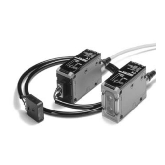
RGB Color Sensor
RGB Color Sensor Discriminates
Delicate Differences in Color.
Best Color Sensor in the Industry.
■
Built-in LED light source ensures long service life
and maintenance-free operation.
■
Discriminates differences in color without being
influenced by changes in ambient temperature,
brightness of sensing objects, or positioning of
sensing objects.
■
Models with built-in amplifiers for long-distance
sensing and those with fiber heads for tiny spot
sensing are available.
■
Incorporates easy-to-see detection level and
threshold level indicators.
■
Degree of protection to IP66 and easy to main-
tain.
■
4-color registration/4-output models are also
available.
Ordering Information
RGB Color Sensor
■
Type
Model
Built-in
E3MC-A11
Amplifier
E3MC-A41
Type
E3MC-MA11
E3MC-MA41
Optical
E3MC-X11
Fiber Type
E3MC-X41
E3MC-MX11
E3MC-MX41
General-
E3MC-Y11
purpose
E3MC-Y41
Optical
E3MC-MY11
Fiber Type
E3MC-MY41
Note:
1. Refer to Specifications on page 3.
2. Eleven colors are discriminated at this distance. For a typical example, nine colors are discriminated at a sensing distance of 12
mm. Refer to page 6 for the definition of sensing distance.
Appearance
The shape of the
amplifier section is
the same as for the
E3MC-(M)A@@.
E32-CC200
E32-T16
Sensing distance
(See note 1)
(See note 1)
Standard sensing distance
5 mm
(See note 2)
200 mm
E3MC
Spot
No. of
diameter
outputs
12 mm
1
NPN
PNP
4
NPN
PNP
3 mm
1
NPN
PNP
4
NPN
PNP
Varies with
1
NPN
the recom-
PNP
mended fi-
4
NPN
ber.
PNP
Output
1
Advertisement

Subscribe to Our Youtube Channel
Related Manuals for Omron E3MC Series


Summary of Contents for Omron E3MC Series
- Page 1 RGB Color Sensor E3MC RGB Color Sensor Discriminates Delicate Differences in Color. Best Color Sensor in the Industry. ■ Built-in LED light source ensures long service life and maintenance-free operation. ■ Discriminates differences in color without being influenced by changes in ambient temperature, brightness of sensing objects, or positioning of sensing objects.
- Page 2 E3MC E3MC Accessories (Order Separately) ■ Name Sensor I/O Connector Name Sensor Mounting DIN-track Mounting Bracket Bracket A replacement or cord extension for a total of 5 m. When mounting the When mounting to the E3MC. (Can be inclined DIN track. Model E39-C1 2M (2 m) E39-C1 5M (5 m)
- Page 3 E3MC E3MC Specifications Ratings/Characteristics ■ Item Built-in amplifier type Optical fiber type General-purpose optical fiber type E3MC-A@1, E3MC-MA@1 E3MC-X@1, E3MC-MX@1 E3MC-Y@1, E3MC-MY@1 Light source Red (680 nm), green (525 nm), and blue (450 nm) LEDs Sensing distance 60±10 mm (see note 1) 20±4 mm (see note 1) Varies with the recommended fiber.
- Page 4 E3MC E3MC Item Built-in amplifier type Optical fiber type General-purpose optical fiber type E3MC-A@1, E3MC-MA@1 E3MC-X@1, E3MC-MX@1 E3MC-Y@1, E3MC-MY@1 Discriminating color 4 banks selectable (either by bank selection input or by using the SELECT button) selection (1-output Input response time for bank selection: 50 ms max. model only) Indicator Operation indicator (orange LED), 4-level bank indicator (green LED, see note 2), 7-level threshold indicator...
- Page 5 E3MC E3MC Engineering Data Angle Characteristics Angle Characteristics Sensing Distance vs. Color (Typical) (When Teaching at an Differences (Typical) Inclination of 15°) E3MC-(M)A@@ E3MC-(M)A@@ (X Direction) E3MC-(M)A@@ (Y Direction) Sensing object: Sensing object: Blue/Green Blue/Green 30 x 27 mm 30 x 27 mm Detection Detection level...
- Page 6 E3MC E3MC Definition of Sensing Distance of a Reflective Recommended Fiber: Through-beam Fiber Fiber The following optical fibers are recommended for use with the E3MC-(M)Y@@. The sensing distance of reflective fiber is the sensing distance of the Sensor located obliquely to the sensing object as shown in Model Sensing distance (see note) the following illustration.
- Page 7 E3MC E3MC Available Optical Fibers In addition to the previous recommended optical fibers, the following optical fibers are available for the E3MC-(M)Y@@. Refer to the E3X- NH Datasheet (E258-E1) for the following optical fibers in detail. Optical fibers other than the following are not available. Model Sensing method Remarks...
-
Page 8: Output Circuits
E3MC E3MC *Function Switch The following settings are possible in RUN or ADJ mode. In case of 4-output models, all channels are subject to the selection of the follow- ing settings. Each pin of the function switch is factory-set to the upper position. (6 ms) 3 ms Note: Figures in parentheses are for the 4-output models. - Page 9 E3MC E3MC E3MC-@41 with PNP Output (1-output Models) Operation indicator (orange) Brown 8-level detection External synchronous indicator (green) 7-level input Pink threshold indicator 4-level bank (red) Bank selection input 2/ indicator Not used Green (green) Bank selection input 1/ Remote control input Main circuit Not used/Answer-...
- Page 10 E3MC E3MC Settings ■ 1-output Models (E3MC-A@@/E3MC-X@@/E3MC-Y@@) 1. Bank Selection Set the Mode Selector to the TEACH mode and then select the BANK using the SELECT button. 2. Color Registration Sensor Registered object All the red threshold indicators will flash if registration has not All the detection level No Good been completed.
- Page 11 E3MC E3MC 4-output Models (E3MC-MA@@/E3MC-MX@@/E3MC-MY@@) 1. Channel Selection Set the Mode Selector to the TEACH mode and then select the channel using the SELECT button. 2. Color Registration Sensor Registered object All the red threshold indicators will flash if registration has not All the detection level No Good been completed.
-
Page 12: Technical Guide
E3MC E3MC Detection Level and Indicator ■ Indicator Detection level Technical Guide ■ Feed workpieces and OK: All Detection Level check if they are detected. Detection of Metal or Glossy Objects Indicators (green) lit. If the E3MC does not detect metal or glossy objects accurately, change the mounting angle of the E3MC so that it will not receive Bring the fiber head as close as possible to the workpiece and... -
Page 13: Mode Setting
E3MC E3MC External Synchronous Input Function ■ The measurement results will be directly output to the control output if the input from the external synchronous input terminal (pink) is set to OFF. The output will hold the previous status if the input of the external synchronous input terminal is set to ON. External synchronous input is valid in RUN or ADJ mode. - Page 14 E3MC E3MC The following is an example of ladder programming. 00000 TIM000 TIM000 set value No.1: 0003 00100 #XXXX No.2: 0006 No.3: 0009 No.4: 00012 TIM000 No.5: 00015 Input: 00000 00100 Output: 00100 Others: Work bits The following is an example of a timing chart of teaching after bank selection. Input detection.
- Page 15 E3MC E3MC Dimensions Note: All units are in millimeters unless otherwise indicated. RGB Color Sensors ■ E3MC-A@@ Mounting Dimensions E3MC-MA@@ Side Mounting Two, 5.5-dia. holes Two, M2.6 x 6 Receiver Four, M5 holes on both sides (depth: 5.5) Bottom Mounting Emitter Four, 5.5-dia.
- Page 16 E3MC E3MC E3MC-Y@@ Mounting Dimensions E3MC-MY@@ (Amplifier Unit) Side Mounting Fiber Unit mounting screw Two, 5.5-dia. holes Two, M2.6 x 6 Four, M5 holes on both sides (depth: 5.5) Receiver section Bottom Mounting Four, 5.5-dia. holes Emitter section Two, 2.4 dia. M12 connector Four, M5 holes (depth: 5.5) Accessories (Order Separately) (2-m Cord is Provided with the E3MC)
- Page 17 E3MC E3MC DIN-track Mounting Bracket E39-L115 When using the E3MC-@A Mounting Bracket Two, M3 Two, M3 Four, 5.5 dia. DIN track Four, M5 Material: Stainless steel (SUS430) Installation Plug (Sensor I/O Connector) ■ Connection E39-C1 2M E39-C1 5M Pin no. Wire Purpose Internal Wiring...
- Page 18 E3MC E3MC Precautions General Mounting Tighten the Fiber Unit with a screwdriver to a torque of 0.2 N·m. Do not impose any voltage exceeding the rated voltage on the E3MC, otherwise the E3MC may be damaged. Fibers When supplying power to the E3MC, make sure that the polarity Among the recommended fibers, the E32-CC200 and E32-D32L of the power is correct, otherwise the E3MC may be damaged.
- Page 19 E3MC E3MC Connection Installation Do not pull the Fiber Unit with force exceeding 9.8 N or press the Power Reset Time Fiber Unit with force exceeding 29.4 N. The E3MC is ready to sense objects from 100 ms after the E3MC The fiber is so thin that the utmost attention will be required to is turned ON, until when no devices connected the E3MC can be handle the fiber.
- Page 20 This document provides information mainly for selecting suitable models. Please read the Instruction Sheet carefully for information that the user must understand and accept before purchase, including information on warranty, limitations of liability, and precautions. In the interest of product improvement, specifications are subject to change without notice. OMRON Corporation Industrial Automation Company Sensing Devices Division H.Q.
- Page 21 Warranty and Limitations of Liability WARRANTY OMRON's exclusive warranty is that the products are free from defects in materials and workmanship for a period of one year (or other period if specifi ed) from date of sale by OMRON. OMRON MAKES NO WARRANTY OR REPRESENTATION, EXPRESS OR IMPLIED, REGARDING NON-INFRINGEMENT, MERCHANTABILITY, OR FITNESS FOR PARTICULAR PURPOSE OF THE PRODUCTS.
Need help?
Do you have a question about the E3MC Series and is the answer not in the manual?
Questions and answers