Advertisement
Quick Links
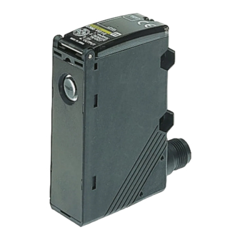
Color Mark Sensor with Teach Function
High-speed Registration Mark
Detection
H
Fast 50 µs response
H
Pushbutton programming for quick
setup
H
Remote control setup for on-the-fly
adjustments
H
Green LED detects yellow-on-white and
other difficult color combinations
H
Stable operation even on shiny surfaces
H
IP67 watertight construction
Ordering Information
J SENSOR
Shape
Sensing
distance
10 3 mm
J MOUNTING BRACKETS
Order mounting brackets separately. These are not included with the sensor.
Shape
R
Light source
Output
Spot size (W x H) and
orientation
Green LED
NPN
1 x 4 mm
(525 nm)
4 x 1 mm
1 x 4 mm
PNP
4 x 1 mm
E3M-V
Part number
Part number
(Quick-disconnect)
(Pre-leaded)
E3M-VG11
E3M-VG17
E3M-VG21
E3M-VG27
E3M-VG16
E3M-VG12
E3M-VG26
E3M-VG22
Part number
E39-L131
E39-L132
Advertisement

Related Manuals for Omron E3M-V


Summary of Contents for Omron E3M-V
- Page 1 Color Mark Sensor with Teach Function E3M-V High-speed Registration Mark Detection Fast 50 µs response Pushbutton programming for quick setup Remote control setup for on-the-fly adjustments Green LED detects yellow-on-white and other difficult color combinations Stable operation even on shiny surfaces...
-
Page 2: Specifications
E3M-V E3M-V J CONNECTING CABLES Shape Type Conductors Length Part number Straight 4-wire 2 meter (6.56 ft) Y96E43SD2 5 meter (16.40 ft) Y96E43SD5 L-shaped 2 meter (6.56 ft) XS2F-D422-D80-A 5 meter (16.40 ft) XS2F-D422-G80-A Specifications J RATINGS/CHARACTERISTICS Part number E3M-VG11... -
Page 3: Engineering Data
E3M-V E3M-V Engineering Data J SENSING DISTANCE VS. J ANGLE VS. INCIDENT J ANGLE VS. INCIDENT INCIDENT CHARACTER- CHARACTERISTICS CHARACTERISTICS ISTICS (TYPICAL) (X DIRECTION) (Y DIRECTION) E3M-VG1j E3M-VG1j/VG2j E3M-VG1j/VG2j Distance (mm) Angle ( ) Angle ( ) J COLOR SENSING BACKGROUND VS. - Page 4 E3M-V E3M-V J INSTALLATION J STANDARD TARGET OBJECT (COLOR VS. MUNSELL) Glossy Target Objects Incline the Sensor for glossy objects to reduce mirror reflection for 11 standard colors Munsell color notation stable sensing operation. White N9.5 4R, 4.5/12.0 Yellow red 4YR, 6.0/11.5...
-
Page 5: Operation
E3M-V E3M-V Nomenclature J E3M-V SENSOR Threshold Indicators (Red) Operation Indicator (Orange) Displays the threshold level. Lit when the output is ON. Mode Selector Detection Level Indicators (Green) Selects the mode. Displays the detection level. SET Button UP/DOWN Selector Used for teaching and threshold Increases the threshold value when adjustments. - Page 6 J OPERATING PROCEDURE Adjustment Steps 1. Install, wire, and turn ON the E3M-V. 2. Perform teaching (mark registration). Refer to Mark Registration (Teaching) . 3. Make fine adjustments of the threshold level if necessary. Refer to Threshold Level Adjustments .
- Page 7 Output Input Upper threshold limit Note: Be sure to connect the E3M-V to the Programmable Con- troller as shown above. Precautions when Using Automatic Teaching Press Incorrect discrimination may be caused by automatic teaching in the following cases. Use one-point or two-point teaching in such The threshold level decreases.
- Page 8 Detection Level Indicator Remote Control Function (Bank Selection, Mark Registration, and Threshold Adjustments) The control output of the E3M-V will be turned ON if the detection level exceeds the threshold level. The indication of the detection Under Run Mode or Adjust Mode level varies with the teaching method.
- Page 9 E3M-V E3M-V Control Signals Ladder Program Example Control signals are input by a ladder program as shown below. Control signal Function Bank 1 is selected TIM000, TIM001, and TIM002 (operation indicator OFF in set values TEACH mode) Bank 2 is selected...
- Page 10 E3M-V E3M-V Dimensions Unit: mm (inch) J COLOR MARK SENSORS Eight detection level indicators Seven level threshold indicators Operation indicator M2.6 47.7 (1.88) M2.6 nut Mounting Holes 10 (0.39) dia. lens Optical axis (1.77) Two, 4.5 dia. Two, M4 mounting holes (0.98)
- Page 11 E3M-V E3M-V J MOUNTING BRACKETS (0.25) 2-R3.2 E39-L131 (0.87) (0.22) 11.5 (0.45) 23.5 (0.93) 6.4 (0.25) 2-R3.2 (1.38) 4-R1 (0.06) (0.98 0.004 (0.98 0.004 (0.17) (0.17) 65.5 (2.58) 4-R2.1 35.5 Two, (1.40) 4.2 dia. 23.5 (0.93) 8.5 (0.33) (1.77) Material: Stainless steel (SUS304) E39-L132 (0.25)
-
Page 12: Installation
E3M-V E3M-V J SENSOR CABLES Single-end Connector (Straight Model) Y96E43SD2 (2 m) Y96E43SD5 (5 m) 6 (0.24) dia. 5 (0.20) dia. 14.9 (0.59) dia. 40.7 (1.60) (0.20) (1.18) (1.97) Single-end Connector (L-shaped Model) XS2F-D422-D80-A (2 m) XS2F-D422-G80-A (5 m) 25.3 6 (0.24) dia. - Page 13 The E3M-V may output a single pulse when the control power An EEPROM error may result if power supply to the Sensor fails supply is turned OFF. If the E3M-V is connected to a timer or or the Sensor is influenced by static noise, and the threshold counter to which power is supplied from an independent power level indicators will flash.
- Page 14 E3M-V E3M-V NOTE: DIMENSIONS SHOWN ARE IN MILLIMETERS. To convert millimeters to inches divide by 25.4. OMRON ELECTRONICS, INC. OMRON CANADA, INC. One East Commerce Drive 885 Milner Avenue Schaumburg, IL 60173 Scarborough, Ontario M1B 5V8 1-800-55-OMRON 416-286-6465 Cat. No. CEDSAX3 10/99 Specifications subject to change without notice.
Need help?
Do you have a question about the E3M-V and is the answer not in the manual?
Questions and answers