Advertisement
Quick Links
Thank you for choosing Sanus Systems Component Furniture. Please check carefully to make sure there are no missing or
defective parts. Never use defective parts. Improper assembly may cause damage or serious injury. If you have any ques-
tions regarding this product, contact Sanus at 800.359.5520 or visit www.sanus.com. Our customer service representatives
can quickly assist you with missing or damaged parts. Replacement parts for Sanus products purchased through authorized
dealers can be shipped directly to you. Please call Sanus Systems before returning products to the point of purchase.
Required Tools: Phillips screw driver
NOTE: Check to make sure all of the parts and hardware are accounted for.
Hardware: Shown at actual size.
Carpet Spike & Nut - A
Qty. 4
Mounting Block Screw - E
Qty. 8
Threaded Cam Pin - I
Qty. 4
Bottom Shelf Pin - M
Qty. 4
Knob - P
Qty. 2
Sanus Systems 2221 Hwy 36 West, Saint Paul, MN 55113 02.16.06 (000022)
Customer Service: 800.359.5520. See complementary Sanus products at www.sanus.com
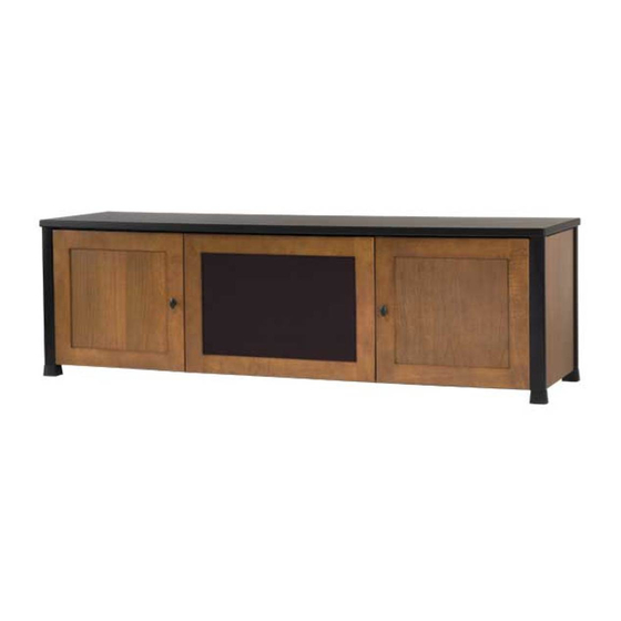
Assembly instructions for Model: CFV69
Cam Pin - B
Qty. 8
Glass Shelf Pin - F
Qty. 4
Barrel Nut - J
Qty. 4
Wood Screw - N
Hinge Screw - Q
Hinge Plate Screw - R
Qty. 8
Back Panel Spacer - C
Qty. 12
Shelf Pin - G
Qty. 8
Barrel Nut Bolt - K
Qty. 4
Qty. 4
Qty. 8
Back Panel Bolt - D
Qty. 12
Dowel - H
Qty. 6
Isolation Pad - L
Qty. 8
Knob Bolt - O
Qty. 2
Allen Key - S
Qty. 1
Advertisement

Related Manuals for Sanus Systems CFV69


Summary of Contents for Sanus Systems CFV69
- Page 1 Assembly instructions for Model: CFV69 Thank you for choosing Sanus Systems Component Furniture. Please check carefully to make sure there are no missing or defective parts. Never use defective parts. Improper assembly may cause damage or serious injury. If you have any ques- tions regarding this product, contact Sanus at 800.359.5520 or visit www.sanus.com.
- Page 2 Parts: Foot - T Cntr. Panel Mtg. Block - U Bottom Shelf Retainer - V Hinge - W Hinge Plate - X Qty. 4 Qty. 4 Qty. 2 Qty. 4 Qty. 4 Bottom Shelf - Z Top - Y Qty. 1 Qty.
- Page 3 WARNING: The ends of the Carpet Spikes are very sharp and may scratch fl oors or furniture. All sharp objects can be hazardous to children. For this reason Sanus Systems provides the carpet spikes as an option. Sanus Systems will not be liable for damage or injury.
- Page 4 Step 3: Add second Side Panel Assembly Attach the second Side Panel Assembly (GG) by sliding the clamp in the Front Rail (AA) and the Cam Pins (B) in the Back Rail (BB) down the grooves in the Pillars on the Side Panel until they are at the bottom of the Pillar and resting on the Foot (T).
- Page 5 Step 5: Add Center Dividers Insert a Barrel Nut (J) into the top and bottom of the Left and Right Center Dividers (HH,II) as in Detail A, Diagram 5. NOTE: Make sure the threaded hole in the Barrel Nut (J) lines up with the hole in the back of the Center Dividers (HH,II), and the arrow on the Cam is pointing toward the hole in the bottom as in Detail B, Diagram 5.
- Page 6 Step 6: Add Top Rails Flange NOTE: Make sure the Flange on the Front Rail (AA) faces the back of the unit. Attach the Front Rail (AA) to the Side Panel Assemblies (GG) by sliding the clamp down the groove in each Side Panel Pillar as done in Step 2.
- Page 7 Step 8: Add Bottom Shelf Retainer Gently rotate the cabinet so it is resting on its back; then, using the Wood Screws (N) secure the Bottom Shelf Retainers (V) to the Bottom Shelf (Z). Diagram 8 Step 9: Add the Back Panels Insert a Back Panel Bolt (D) through the Outer Back Panels (CC), Center Back Panel (DD), and a Spacer (C);...
- Page 8 Step 10: Add Top Insert a Dowel (H) into each hole in the bottom of the Top (Y). Align the Dowels (H) in the bottom of the Top (Y) with the holes in the Center Dividers (HH,II) and the pillars on the Side Panels (GG);...
- Page 9 Step 12: Add Isolation Shelves Insert two Shelf Pins (G) per Side Panel Assembly (GG) and two Shelf Pins per Center Divider (HH, II) at the desired height. Align the holes on the bottom side of the Isolation Shelves (EE) with the Shelf Pins (G), and place the Isolation Shelf on the Shelf Pins.
- Page 10 Step 14: Add Center Panel Mounting Blocks Attach the Center Panel Mounting Blocks (U) to the Center Dividers (HH,II) by threading the Mounting Block Screws (E) through the Mounting Blocks and into the Center Dividers. Tighten each Mounting Block Screw with a phillips screw driver. Repeat until all four Mounting Blocks are in place.
- Page 11 Step 16: Prepare the Doors Insert a Knob Bolt (O) through the backside of the Side Door (KK) and thread it into the Knob (P). Tighten the Knob until it is fl ush with the front side of the Side Door. Perform this procedure for both Side Doors. Diagram 16 Step 17: Attach Hinge to Side Door Attach the Hinges (W) to the Side Doors (KK) by threading a Hinge Screw (Q) through each hole in the Hinge and into the...
- Page 12 Each hinge Assembly is adjustable in multiple directions. Diagram 19 Side Adjustment Depth Adjustment Height Adjustment 1 . 5 + / - Sanus Systems 2221 Hwy 36 West, Saint Paul, MN 55113 02.16.06 (000022) Customer Service: 800.359.5520. See complementary Sanus products at www.sanus.com...
Need help?
Do you have a question about the CFV69 and is the answer not in the manual?
Questions and answers