Advertisement
Quick Links
Advertisement

Related Manuals for Major tech MTD75T


Summary of Contents for Major tech MTD75T
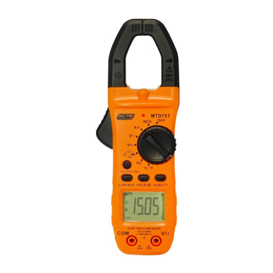
- Page 1 MTD75T 800A AC/DC True RMS Digital Clamp Meter Instruction Manual...
-
Page 2: Safety Notes
Safety International Safety Symbols This symbol, adjacent to another symbol or terminal, indicates the user must refer to the manual for further information. This symbol, adjacent to a terminal, indicates that, under normal use, hazardous voltages may be present. Double insulation. Application around and removal from uninsulated hazardous live conductors is permitted. - Page 3 CAUTIONS • Improper use of this meter can cause damage, shock, injury or death. Read and understand this user manual before operating the meter. • Always remove the test leads before replacing the battery or fuses. • Inspect the condition of the test leads and the meter itself for any damage before operating the meter.
- Page 4 Description Meter Description NCV Test Current clamp LED Flashlight Non-contact AC voltage indicator light Clamp trigger Rotary Function switch SELECTOR mode range button Data Hold and Flashlight and LCD backlight button RANGE button and DCA Zero Frequency and % Duty Cycle button LCD display COM input jack V Ω...
- Page 5 Display icons Description Data Hold Minus sign Negative reading display 0 to 5999 Measurement display digits DCA Zero Non-Contact Voltage Auto Power Off AUTO Auto Range mode Direct Current/Voltage Alternating Current/Voltage Low battery mV or Milli-volts or Volts (Voltage) Ω Ohms (Resistance) Amperes (Current) Farad (Capacitance)
- Page 6 Specifications Function Range Resolution Accuracy (% of reading + digits) AC True 60.00A 0.01A ±1.5% of rdg ± 5 600.0A 0.1A digits Current 800.0A Over range protection: Maximum input 1000A Accuracy specified from 5% to 100% of the measuring range Frequency Response: 40Hz to 1kHz True RMS Function Range...
- Page 7 Resoluti Accuracy Function Range (% of reading + digits) 600mV 0.1mV ±1.0% of rdg ± 5 digits 6.00V Voltage 60.0V 10mV ±0.5% of rdg ± 5 digits 600V 100mV Input impedance 10MΩ. Overload protection 1000Vrms Accuracy Function Range Resolution (% of reading + digits) ±0.8% of rdg ±...
- Page 8 Accuracy Function Range Resolution (% of reading + digits) ± (5.0% rdg ± 10 digits) 60nF 10pF 600nF 100pF ± (2.5% rdg Capacitance ±5 digits) (Auto- ranging) 60uF 10nF 600uF 100nF ± (5% rdg ± 10 digits) 60mF 10uF Ensure capacitors are discharged before measuring value Warning DO NOT apply voltage to this range Accuracy Function...
- Page 9 Accuracy Function Range Resolution (% of reading + digits) -40°C to 400°C: 1.0% 5°C < ± ± 1°C +1000°C 400°C: 1.5% 15°C ≥ ± ± Temperature 0°F to 750°F: 1.0% 5°C < ± ± 1°F +1832°F 750°F: 1.5% 15°C ≥ ±...
-
Page 10: Operation
Input Impedance 10M (VDC and VAC) AC response True rms (AAC and VAC) ACV Bandwidth 2KHZ Operating Temperature 5 C to 40 C (41 F to 104 Storage Temperature C to 60 C (-4 F to 140 Operating Humidity Max 80% up to 31 C (87 Decreasing linearly to 50% at 40 (104... - Page 11 AC Current Measurements WARNING: Ensure that the test leads are disconnected from the meter before making current clamp measurements. Set the Function switch to the Range. If the approx. range of the measurement is not known, select Auto Range. △/ Press the RANGE button to zero the meter display.
- Page 12 AC Voltage Measurement Insert the black test lead into the negative COM terminal and the red test lead into the positive V/ terminal. Set the function switch to the position. Connect the test leads in parallel to the circuit under test.
- Page 13 Resistance Measurement Insert the black test lead into the negative COM terminal and the red test lead into the positive V/ terminal. Set the function switch to the position. Use SELECT Button to select Touch the test probe tips across the circuit or component under test.
- Page 14 Frequency Measurement Insert the black test lead into the negative COM terminal and the red test lead into the positive V/ terminal. Set the function switch to the position. Touch the test probe tips across the circuit or component under test. It is best to disconnect one side of the device under test so the rest of the circuit will not interfere with the resistance reading.
- Page 15 Continuity Measurements Insert the black test lead into the negative COM terminal and the red test lead into the positive V/ terminal. Set the function switch to the position Use SELECT Button to select . The display icons will change when the SELECT button is pressed. Touch the Test Probe tips across the circuit or component under test.
- Page 16 Non-Contact AC Voltage Measurements WARNING: Risk of Electrocution. Before use, always test the Voltage Detector on a known live circuit to verify proper operation Touch the probe tip to the hot (LIVE) conductor or insert into the hot (LIVE) side of the electrical outlet. If AC voltage is present, the detector red LED light will illuminate.
- Page 17 RANGE Press the RANGE key to activate the manual mode and to disable the Auto range function. The symbol “AUTO” disappears from the upper left part of the display. In manual mode, press the RANGE key to change measuring range: the relevant decimal point will change its position.
- Page 18 Cleaning and Storage Periodically wipe the case with a damp cloth and mild detergent; do not use abrasives or solvents. If the meter is not to be used for 60 days or more, remove the battery and store it separately. Battery Replacement When the LCD displays ,please replace the battery...
Need help?
Do you have a question about the MTD75T and is the answer not in the manual?
Questions and answers