Advertisement
Advertisement
Table of Contents

Related Manuals for Major tech MT930


Summary of Contents for Major tech MT930
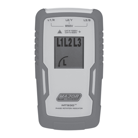
- Page 1 INSTRUCTION MANUAL MT930 PHASE ROTATION INDICATOR...
- Page 3 Contents Page no 1. Introduction ..................4 2. Symbols ..................4 3. Safety Information ................4 4. The Phase Rotation Indicator Ships with the Following Items ....5 5. Elements of the Phase Rotation Indicator ..........5 6. Determine Rotary Field Direction ............6 7. Specifications ...................6...
- Page 4 1. INTRODUCTION The phase rotation indicator is a handheld instrument designed to detect the rotary field of three-phase systems. 2. SYMBOLS The following symbols appear on the Motor and Phase Rotation indicator or in this manual. Risk of electric shock Risk of Danger, Important information see manual.
- Page 5 • Measurements can be adversely affected by impedances of additional operating circuits connected in parallel or by transient currents. • Verify operation prior to measuring hazardous voltages (voltages above 30V AC RMS, 42V AC peak and 60V DC). • Do not use the phase rotation indicator with any of the parts removed. •...
- Page 6 6. DETERMINE ROTARY FIELD DIRECTION 1. Connect the test probes to the end of the test leads. 2. Connect the test probes to the three mains phases. 3. The green ON indicator shows that the instrument is ready for testing. 4.
- Page 8 MAJOR TECH (PTY) LTD South Africa Australia www.major-tech.com www.majortech.com.au sales@major-tech.com info@majortech.com.au...
Need help?
Do you have a question about the MT930 and is the answer not in the manual?
Questions and answers