Table of Contents
Advertisement
Quick Links
Advertisement
Table of Contents

Related Manuals for Major tech MT715


Summary of Contents for Major tech MT715
- Page 1 INSTRUCTION MANUAL MT715 AC TRMS OPEN JAW CLAMP METER...
-
Page 3: Table Of Contents
Contents Page no 1. lntroduction ................4 2. Safety ..................4 3. Description ................. 6 3.1. Meter Description ............... 6 3.2. Symbols Used on LCD Display ..........7 4. Specifications ................8 4.1. Specifications ..............8 4.2. General Specifications ............9 5. -
Page 4: Lntroduction
1. lntroduction The MT715 is a hand held digital open jaw clamp meter. The instrument LCD adopts a negative display, rotary switch with backlight indication, which facilitates the user to operate the instrument under dark/dim conditions. The MT715 is idea for Industrial and domestic applications where high current measurement is required. - Page 5 2.2. Safety Notes • Do not exceed the maximum allowable input range of any function. • Do not apply voltage to meter when resistance function is selected. • Set the function switch OFF when the meter is not in use. •...
-
Page 6: Description
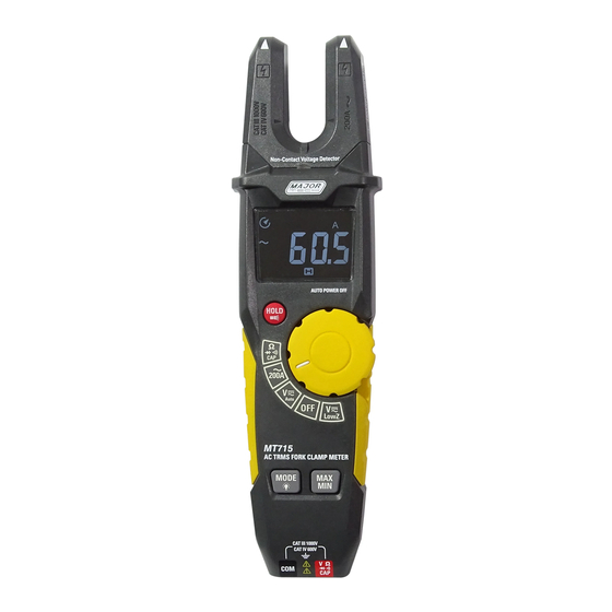
3. Description 3.1. Meter Description 1-NCV Indicator Test 8-Data Hold and Flashlight Button 2-Current Fork 9-M0DE and Backlight Button 3-Non-Contact AC Voltage Indicator Light 10-MAX/MIN Button 4-Negative LCD Display 11-Flashlight 5-Knob Indicator - Backlit 12-Battery Cover 6-Rotary Selector Switch 13-COM Input Jack 7-Range Markings - Backlit 14-V Ω... -
Page 7: Symbols Used On Lcd Display
3.2. Symbols Used on LCD Display 1-Alternating Voltage and Current 2-Minus Sign 3-Direct Voltage and Current 4-Auto Power Off 5-Auto Range Mode 6-Continuity Test 7-Diode Test 8-Low Battery 9-Units of Measure List 10-Measurement Display Digits 11-Maximum/Minimum 12-Data Hold 13-Low Impedance Input Mode... -
Page 8: Specifications
4. Specifications 4.1. Specifications Range Resolution Function Accuracy ±(% of reading+digits) 100mA ±(3% + 5 digits) 200.0A AC Current Over range protection: Maximum input 200A. Frequency Response: 50 to 60Hz Range Resolution Accuracy ±(% of reading+digits) Function 6.000V ±(1.2% + 5 digits) AC True RMS Voltage (Auto Ranging) 60.00V... -
Page 9: General Specifications
Testing Condition Function Reading Test current of 1.5mA typical Forward voltage drop of Diode Diode Open circuit voltage <3VDC typical Continuity Test current <0.35mA Buzzer makes a long sound, While resistance is less than (50Ω) Over Range Protection: 300V RMS. 4.2. -
Page 10: Operation
5. Operation NOTES: Read and understand all WARNING and CAUTION statements in this operation manual prior to using this meter. Set the function select switch to the OFF position when the meter is not in use. 5.1. AC Current Measurements WARNING: Ensure that the test leads are disconnected from the meter before making current clamp measurements. -
Page 11: Low Z Voltage Measurements
5.3. Low Z Voltage Measurements NOTES: Observe all safety precautions when working on live voltages. Do not connect to circuits that exceed 600V AC/DC when the meter is set to Low Z. Low Z is used when there is a suspicion of a "ghost" voltage. Ghost voltages are present when non-powered wires are in close proximity to wires powered by AC voltage. -
Page 12: Capacitance Measurements
5.6. Capacitance Measurements WARNING: To avoid electric shock, discharge the capacitor under test before measuring. Set the function switch to the Ω CAP position. lnsert the black test lead banana plug into the negative COM jack and the red test lead banana plug into the V Ω CAP positive jack. -
Page 13: Button
6. Button 6.1. MODE and Backlight Button • Press MODE and Backlight Button to select OHM/Diode/Continuity/CAP/ LoZ AC/DC Voltage. • Press the MODE and Backlight button for over 1 second to turn the button, Knob and Rotary light on. • Press again for over 1 second to turn the button, Knob and Rotary light off. -
Page 14: Maintenance
8. Maintenance WARNING: To avoid electrical shock, disconnect the meter from any circuit, remove the test leads from the input terminals, and turn OFF the meter before opening the case. Do not operate the meter with an open case. Cleaning and Storage Periodically wipe the case with a damp cloth and mild detergent;... - Page 16 MAJOR TECH (PTY) LTD South Africa Australia www.major-tech.com www.majortech.com.au sales@major-tech.com info@majortech.com.au...
Need help?
Do you have a question about the MT715 and is the answer not in the manual?
Questions and answers