
Related Manuals for Major tech MT775


Summary of Contents for Major tech MT775
- Page 1 MT775 AC TRUE RMS CLAMP METER INSTRUCTION MANUAL © 2004, MAJOR TECH (PTY) LTD. All rights reserved...
-
Page 2: Table Of Contents
CONTENTS Measuring Limits ......Safety Warnings ......Features ......... 4 Instrument Layout ......5 Specifications ........ 5 Data Hold Function ......7 Peak Hold Function ......7 LCD Backlight ......... 7 AC Current Measurement ....8 10. DC Voltage Measurement ....9 11 AC Voltage Measurement ..... -
Page 3: Safety Warnings
If the meter is not used in a manner specified in this manual, the protection provided by the meter may be impaired The Model MT775 has been designed and complies with IEC 61010-1 and EN 61010-1 Safety Requirements for Electronic Measuring Apparatus. - Page 4 DANGER Never use the meter to measure voltages on a circuit above the maximum allowable input value on any function. Do not exceed the maximum allowable input of any measurement range. Never touch exposed wiring, connections or any live circuit when attempting to take measurements.
-
Page 5: Features
CAUTION Before making measurements ensure that the function selector switch is set on the appropriate range position. Always make sure that the plug of each test lead is inserted fully into the appropriate terminal of the meter. Ensure that the function selector switch is set to the “OFF”... -
Page 6: Instrument Layout
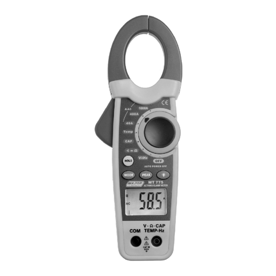
4. INSTRUMENT LAYOUT Transformer Jaws Jaw Trigger Function Switch Data Hold Switch Backlight Mode Switch Switch Peak Hold Display with Selector Switch Bargraph for Volts and Current Volt, Resistance, Frequency, Terminal Temperature Terminal 5. SPECIFICATIONS Clamp Size 30mm Opening Approx Diode Test Test Current of 0.3mA typical;... - Page 7 5. SPECIFICATIONS AC Current Range Measuring Range Resolution Accuracy (% of Reading) 0 ~ 40.00A 0.01 A ± (2.8% + 10 digits) 400A 0 ~ 400.0A 0.1 A ± (2.8% + 8 digits) 1000A 0 ~ 1000A ± (3.0% + 8 digits) DC Voltage Range Measuring Range Resolution...
-
Page 8: Data Hold Function
6. DATA HOLD This is a function used to freeze the reading on the display, ideal for later viewing. HOLD 1. Press the button once. When the Hold is activated, the meter beeps, freezes the reading, and displays the “HOLD” indicator on the LCD. -
Page 9: Ac Current Measurement
9. AC TRUE RMS CURRENT MEASUREMENT WARNING: Ensure that the test leads are disconnected from the meter before making current measurements. 1. Set the function switch to 400A 1000A range position, and make sure that the current under test does not exceed the upper limit of the measuring range you have selected. -
Page 10: Dc Voltage Measurement
10. DC VOLTAGE MEASUREMENT _ _ _ _ 1. Set the function switch to range position. The meter automatically defaults to DC Volts. 2. Insert the red test lead into the “V Ω TEMP HZ” input terminal and the black lead to the “COM” terminal. -
Page 11: Ac Voltage Measurement
11. AC TRUE RMS VOLTAGE MEASUREMENT _ _ _ _ 1. Set the function switch to range position. 2. Press the button to select the AC Volt MODE range. The meter automatically defaults to DC Volts. 3. Insert the red test lead into the “V Ω TEMP HZ” input terminal and the black lead to the “COM”... -
Page 12: Resistance Measurement
12. RESISTANCE MEASUREMENT 1. Set the function switch to range Ω position. The meter automatically defaults to resistance range. 2. Insert the red test lead into the “V Ω TEMP HZ” input terminal and the black lead to the “COM” terminal. -
Page 13: Capacitance Measurement
13. CAPACITANCE MEASUREMENT 1. Set the function switch to range position. 2. Insert the red test lead into the “V Ω TEMP HZ” input terminal and the black lead to the “COM” terminal. 3. Connect the other end of the test leads to the circuit or component under test. -
Page 14: Frequency Measurement
14. FREQUENCY MEASUREMENT _ _ _ _ 1. Set the function switch to range position. The meter automatically defaults to Frequency range. 2. Press the button for 3 seconds to select MODE the Frequency range. The meter automatically defaults to DC Volts. 3. -
Page 15: Temperature Measurement
15. TEMPERATURE MEASUREMENT 1. Set the function switch to range position. Temp The meter automatically defaults to ºC range. 2. Insert the MT802 white temperature adaptor into the “V Ω TEMP HZ” input terminal and the “COM” terminal. Ensure that the “-” marking on the adaptor is inserted into the “COM”... -
Page 16: Diode Test
16. DIODE TEST 1. Set the function switch to range Ω position. MODE 2. Press the button to select the Diode Test range. The meter automatically defaults to Resistance. 3. Insert the red test lead into the “V Ω TEMP HZ” input terminal and the black lead to the “COM”... -
Page 17: Continuity Testing
17. CONTINUITY TESTING 1. Set the function switch to range Ω position. MODE 2. Press the button to select the Continuity Test range. The meter automatically defaults to Resistance. 3. Insert the red test lead into the “V Ω TEMP HZ” input terminal and the black lead to the “COM”... -
Page 18: Auto Power Off
18. AUTO POWER OFF This feature automatically turns off the meter after approximately 20 minutes from the last measurement taken. To turn the on the meter, press any button or move the rotary switch to any position. Ensure te test leads are disconnected from any circuit to avoid injury or meter damage 19. -
Page 19: Battery Replacement
21. BATTERY REPLACEMENT When the “ “ sign appears on the LCD, this indicates the battery should be replaced. Use the following procedure to replace the standard 9V battery (IEC 6F 22) battery. 1. Disconnect the test leads from any live source and remove the leads from the input terminals. - Page 20 P .O. Box 888, Isando 1600, South Africa Telephone: +27 11 872 5500 National Contact Number: 08 61 62 5678 Sales Facsimile: +27 11 822 2806 Admin Facsimile: +27 11 822 1411 E-mail: sales@major-tech.com www.major-tech.com © 2004, MAJOR TECH (PTY) LTD. All rights reserved E&OE...
Need help?
Do you have a question about the MT775 and is the answer not in the manual?
Questions and answers