Table of Contents
Advertisement
Quick Links
Advertisement
Table of Contents

Related Manuals for Major tech MT790


Summary of Contents for Major tech MT790
- Page 1 INSTRUCTION MANUAL MT790 1000A AC POWER CLAMP METER...
-
Page 3: Table Of Contents
Contents Page no 1. Overview..................4 2. Unpacking Inspection................4 3. Safety Information................5 4. Rules for Safe Operation..............5 5. The Meter Structure................6 5.1. The Meter Back and Bottom Structure..........6 5.2. The Meter Front Structure............7 6. Function...................8 7. Display Symbols................9 8. Measurement Operation..............10 8.1. -
Page 4: Overview
1. OVERVIEW This Operating Manual covers information on safety and cautions. Please read the relevant information carefully and observe all the Warnings and Notes strictly. WARNING: To avoid electric shock or personal injury, read the "Safety Information" and "Rules for Safe Operation" carefully before using the Meter. -
Page 5: Safety Information
3. SAFETY INFORMATION This Meter complies with the standards IEC61010: in pollution degree 2, overvoltage category (CAT. III 600V, CAT IV 300V) and double insulation. CAT. III: Distribution level, fixed installation, with smaller transient overvoltages than CAT. IV CAT.IV: Primary supply level, overhead lines, cable systems etc. -
Page 6: The Meter Structure
• When opening the battery door, make sure the Meter is off. • When servicing the Meter, use only the same model number or identical electrical specifications replacement parts. • The internal circuit of the Meter shall not be altered at will to avoid damage of the Meter and any accident. -
Page 7: The Meter Front Structure
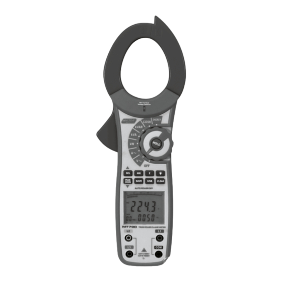
5.2. The Meter Front Structure (see figure 2) Figure 2 1 - Transformer Jaw: designed to 7 - LCD Display pick up the AC and DC current 8 - L2 Input Terminal flowing through the conductor. (Second phase measurement) It could transfer current to 9 - L3 Input Terminal voltage. -
Page 8: Function
6. FUNCTION Below table indicated for information about the functional button operations. Operation Performed Button Press HOLD to enter the Hold mode in any mode, appears and the Meter beeps. HOLD Press HOLD again to exit the Hold mode to return to measurement mode, the Meter beeps and, disappears. -
Page 9: Display Symbols
1. Turn the rotary switch dial to a position away from the OFF position. Hearing a beep sound indicates the meter is turned on. The LCD displays all symbols firstly and then return to the normal mode. If the symbol is displayed, please changed the battery. -
Page 10: Measurement Operation
Operation Performed Button Data Output is in progress First phase symbol Ø1 Ø2 Second phase symbol Ø3 Third phase symbol Unit for hour mm Unit for minute Hz: Hertz.The unit of frequency. PG: The unit of phase angle KVAr KVAr. The unit of reactive power Watt: Sum of Watt The battery is low. -
Page 11: Ac Voltage (Main Display) + Frequency (Secondary Display)
1. Rotate the Function switch to any measurement position. 2. Place the detector probe tip on the conductor to be tested. NOTE: The conductors in electrical cord sets are often twisted. For best results, move the probe tip along a length of the cord to assure placing the tip close to the live conductor. -
Page 12: Ac Current (Main Display) + Ac Voltage (Secondary Display)
4. Press SEL to select phase location, the display shows the corresponding phase symbol. L1 means the first phase , L2 means Ø1 the second phase , L3 means the third phase Ø2 Ø3 5. The display shows the corresponding True RMS voltage value and frequency value of each phase. - Page 13 To measure AC current + AC voltage, connect the Meter as follows: 1. Dial the Rotary to AAC to select AC Current + AC Voltage range. 2. Press the lever to open the transformer jaw. 3. Center the conductor within the transformer jaw, then release the Meter slowly until the transformer jaw is completely closed, Make sure the conductor to be tested is placed at the center of the transformer jaw, otherwise it will cause deviation.
- Page 14 Figure 6 Measuring Instruction 1. Press SEL to choose first phase Ø1 , see figure 7. The double displays show the active power kW value and the PG value of the second phase Figure 7...
- Page 15 If necessary, press Σ to get the sum of watts as figure 8. Figure 8 2. After recording the current power measurement value of the first phase, Ø2 then press SEL to choose . The double display shows the value of active power kW and PG of the second phase 2.
- Page 16 3. After recording the current power meaursuremnt value of the second Ø3 phase, then press SEL again to choose . The double display shows the value of active power KW and PG of the third phase, as in figure 11. Figure 11 If necessary, press Σ...
- Page 17 Press ▲ as figure 14 to step through in sequence threephase sum of active power+three phase sum of reactive power, and three phase sum of power factor + 3 phase sum of apparent power. Figure 14 Press Σ and hold for 1 second again to change back to the normal measuring mode.
-
Page 18: Display) Measurement
1. Insert blue, red test leads to L1, L3 input terminal. 2. Insert black test leads to COM input terminal and connect it to the neutral wire of the 3 phase. 3. Jump over to the second phase measurement. 4. The first and the third phase measuring method is same as 3 phase 4 wires. - Page 19 Figure 18 The double display shows the first phase value of power factor PF and phase angle PG. Then press SEL again to choose the second phase, see figure 19. • Press SEL to choose the second phase, see figure 19. Figure 19 The double display shows the second phase value of power factor PF and phase angle PG.
-
Page 20: Active Energy (Main Display) + Time (Secondary Display) Measurement
5. When measuring 3 phase 3 wires: • The first phase and third phase operating method is same as 3 phase 4 wires. • Jump over the second phase measurement. 6. MAXMIN button are not valid when measuring power factor. 8.8. -
Page 21: True Rms And Average Value Measurement
• The maximum reading of active energy is 9999kWh. OL will be displayed when the reading is over than that. 5. MAXMIN are not valid when measuring active energy. 6. Press CLEAR and hold for 1 seconds to reset the time and energy. Note •... -
Page 22: Specifications
10. SPECIFICATIONS 10.1. Accuracy Function Range (a% reading + b digits) guarantee for 1 year. Operating temperature 23℃±5℃ Operating humidity 45~75%R.H 10.2. AC Voltage (True RMS) Range Resolution Accuracy Allowable Maximum Input Frequency Overload Protection Impedance Range Voltage 100V 0.1V ±(1.2%+5) 750 RMS 50Hz~200Hz 400V... -
Page 23: Apparent Power (Va = V X A)
10.6. Apparent Power (VA = V x A) Current / Voltage Voltages Range 100V 400V 750V Current 4.00KVA 16.00KVA 30.00KVA Range 100A 10.00KVA 40.00KVA 75.00KVA 400A 40.00KVA 160.0KVA 300.0KVA 1000A 100.0KVA 400.0KVA 750.0KVA Accuracy ±(3%+5) Resolution <1000KVA: 0.01KVA 100kW: 0.1KVA θ... -
Page 24: Active Energy (Kwh)
10.10. Active Energy (kWh) Range Resolution Accuracy 1~9999kWh ±(3%+2) 0.001kWh Remarks: • Allowable maximum overload protection voltage: 750V RMS • Allowable maximum overload protection current: 1000A RMS Basic Functions Range Best Accuracy AC Voltage 100V/400V/750V ±(1.2%+5digits) AC Current 40A/100A/400A/1000A ±(2%+5 digits) Active Power 0.01kW-750kW ±(3%+5 digits) - Page 28 MAJOR TECH (PTY) LTD South Africa Australia www.major-tech.com www.majortech.com.au sales@major-tech.com info@majortech.com.au...
Need help?
Do you have a question about the MT790 and is the answer not in the manual?
Questions and answers