Table of Contents
Advertisement
Quick Links
Advertisement
Table of Contents

Related Manuals for Major tech MTD15


Summary of Contents for Major tech MTD15
- Page 1 INSTRUCTION MANUAL MTD15 400A AC CLAMP METER...
-
Page 3: Table Of Contents
Contents Page no 1. Safety..................4 1.1. International Safety Symbols..........4 1.2. Safety Notes...............4 1.3. Warnings................4 1.4. Cautions................4 3. Specifications.................6 4. Operation................7 4.1. AC Current Measurements..........7 4.2. AC/DCVoltage Measurements........7 4.3. Resistance and Continuity Measurements......7 4.4. Diode Measurements.............7 4.5. Data Hold................8 4.6. AC Voltage Measurement..........8 4.7. -
Page 4: Safety
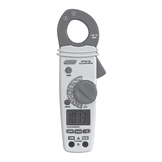
1. SAFETY 1.1. lnternational Safety Symbols This symbol, adjacent to another symbol or terminal, indicates the user must refer to the manual for further information. This symbol, adjacent to a terminal, indicates that, under normal use, hazardous voltages may be present. Double insulation. - Page 5 Input Limits Function Maximum Input A AC 400A V DC, V AC 600V DC/AC Resistance, Diode, Continuity Test 250V DC/AC 2. METER DESCRIPTION 1 - Current clamp 2 - Clamp trigger 3 - Rotary Function switch 4 - LCD display 5 - MAX Hold button 6 - Data Hold button 7 - Mode select button...
-
Page 6: Specifications
3. SPECIFICATIONS Function Range & Resolution Accuracy (% of Reading AC Current 2.000 AAC ±(2.5%+10digits) 20.00 AAC ±(2.5%+4 digits) 200.0 AAC 400 AAC ±(3.0%+4 digits) DC Voltage 200.0 mVDC ± (0.5%+5 digits) 2.000 VDC 20.00 VDC ± (1.2% +3 digits) 200.0 VDC 600 VDC ±... -
Page 7: Operation
3. SPECIFICATIONS continued..Function Range Clamp size Opening 23mm (0.9") approx. Diode Test Test current of 0.3mA typical; Open circuit voltage 1.5V DC typical. Continuity Check Threshold <120Ω; Test current < 1mA Low Battery Indication " BAT" is displayed Overrange Indication "OL "... -
Page 8: Ac/Dcvoltage Measurements
1. Set the Function switch to the 400A or 200A or 20A or 2A range. If the range of the measured is not known, select the higher range first then move to the lower range if necessary. 2. Press the trigger to open jaw. Fully enclose one conductor to be measured. -
Page 9: Data Hold
2. Turn the rotary switch to the position. 3. Press the MODE button until " " appears in the display. 4. Touch the test probes to the diode under test. Forward voltage will indicate 0.4V to 0.7V. Reverse voltage will indicate "OL". Shorted devices will indicate near 0mV and an open device will indicate "OL"... - Page 12 MAJOR TECH (PTY) LTD South Africa Australia www.major-tech.com www.majortech.com.au sales@major-tech.com info@majortech.com.au...
Need help?
Do you have a question about the MTD15 and is the answer not in the manual?
Questions and answers