Advertisement
Quick Links
Advertisement

Related Manuals for Major tech MTD73A


Summary of Contents for Major tech MTD73A
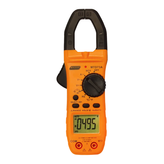
- Page 1 MTD73A 800A AC True RMS Digital Clamp Meter Instruction Manual...
-
Page 2: Safety Notes
Safety International Safety Symbols This symbol, adjacent to another symbol or terminal, indicates the user must refer to the manual for further information. This symbol, adjacent to a terminal, indicates that, under normal use, hazardous voltages may be present. Double insulation. Application around and removal from uninsulated hazardous live conductors is permitted. - Page 3 CAUTIONS • Improper use of this meter can cause damage, shock, injury or death. Read and understand this user manual before operating the meter. • Always remove the test leads before replacing the battery or fuses. • Inspect the condition of the test leads and the meter itself for any damage before operating the meter.
- Page 4 Description Meter Description NCV Test Current clamp LED Flashlight Non-contact AC voltage indicator light Clamp trigger Rotary Function switch SELECTOR mode range button / Flashlight Data Hold button REL button for Relative Measurement Flashlight and LCD backlight button LCD display COM input jack V Ω...
- Page 5 Display icons Description HOLD Data Hold Minus sign Negative reading display 0 to 3999 Measurement display digits Non-Contact Voltage AUTO Auto Range mode Direct Voltage Alternating Current/Voltage Low battery mV or V Milli-volts or Volts (Voltage) Ω Ohms (Resistance) Amperes (Current) Farad (Capacitance) Hz/% Hertz (Frequency)/Percent(duty ratio)
- Page 6 Specifications Accuracy Function Range Resolution (% of reading + digits) < 40A: (3.0% 10mA rdg + 5digits) ˃ 40A: (2% rdg Current 400A 100mA + 5 digits) 800A Over range protection: Maximum input 1000A Accuracy specified from 5% to 100% of the measuring range Frequency Response: 40Hz to 1kHz True RMS Accuracy (% of...
- Page 7 Accuracy Function Range Resolution (% of reading + digits) +1.0% of rdg + 400mV 0.1mV 5digits DC Voltage 4.00V (Auto Ranging) 40.0V 10mV +0.5% of rdg + 5digits 400V 0.1V 600V Input impedance on 400mV range ˃ 40MΩ all other ranges 10MΩ.
- Page 8 Accuracy Function Range Resolution (% of reading + digits) (5% reading + 0.nF 20 digits) 40nF 0.01nF 400nF 0.1nF (2.5% reading Capacitance 0.001µF + 5 digits) (Auto- 40uF 0.01µF ranging) 400uF 100nF (5% reading + 10 digits) 40mF 10uF Input Protection: 250V DC or 250V AC RMS Ensure capacitors are discharged before measuring value Warning DO NOT apply voltage to this range Accuracy...
- Page 9 Accuracy (% of Function Range Resolution reading + digits) < 400°C: +1.0% of rdg + 5°C Temperature -40°C to 1000°C 1°C ≥ 400°C: +1.5% of rdg + 5°C Input Protection: 250V DC or 250V AC RMS Sensor: Type K Banana Plug Thermocouple Warning DO NOT apply voltage to this range Function Testing Condition...
- Page 10 General Specifications Clamp jaw opening 28mm approx. Display 4000 Count (3-3/4 digits backlit LCD Low Battery indication is displayed Over-range indication ‘OL’ display Measurement rate 3 readings per second, nominal Temperature sensor Type K thermocouple 4mm terminals Input Impedance 10M (VDC and VAC) AC response Average Reading (AAC and VAC) ACV Bandwidth...
- Page 11 AC Current Measurements WARNING: Ensure that the test leads are disconnected from the meter before making current clamp measurements. Set the Function switch to the Range. If the approx. range of the measurement is not known, select Auto Range. △/ Press the REL button to zero the meter display.
- Page 12 AC Voltage Measurement Insert the black test lead into the negative COM terminal and the red test lead into the positive V/ terminal. Set the function switch to the position. Connect the test leads in parallel to the circuit under test.
- Page 13 Resistance Measurement Insert the black test lead into the negative COM terminal and the red test lead into the positive V/ terminal. Set the function switch to the position. Use SELECT Button to select Touch the test probe tips across the circuit or component under test.
- Page 14 Frequency Measurement Insert the black test lead into the negative COM terminal and the red test lead into the positive V/ terminal. Set the function switch to the position. Touch the test probe tips across the circuit or component under test. It is best to disconnect one side of the device under test so the rest of the circuit will not...
- Page 15 Continuity Measurements Insert the black test lead into the negative COM terminal and the red test lead into the positive V/ terminal. Set the function switch to the position Use SELECT Button to select . The display icons will change when the SELECT button is pressed. Touch the Test Probe tips across the circuit or component under test.
- Page 16 Non-Contact AC Voltage Measurements WARNING: Risk of Electrocution. Before use, always test the Voltage Detector on a known live circuit to verify proper operation Touch the probe tip to the hot (LIVE) conductor or insert into the hot (LIVE) side of the electrical outlet. If AC voltage is present, the detector red LED light will illuminate.
- Page 17 REL Mode This sets the relative point to measure against the next reading. Press the REL key to enter the Relative Measurement Mode, this function resets the display to zero. Automatic Power OFF In order to conserve battery life, the meter will automatically turn off after approximately 15 minutes.
- Page 18 Battery Replacement When the LCD displays , please replace the battery to ensure correct readings Remove the Phillips head screw that secures the rear battery door Open the battery compartment Replace the 2 x 1.5V AAA battery, recommend Alkaline batteries for longer use Secure the battery compartment...
Need help?
Do you have a question about the MTD73A and is the answer not in the manual?
Questions and answers