Water Right Impression Plus Series Installation Instructions & Owner's Manual
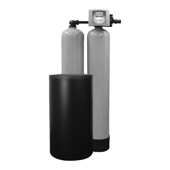
Twin water softeners
Hide thumbs
Also See for Impression Plus Series:
- Installation instructions & owner's manual (36 pages) ,
- Installation instructions & owner's manual (32 pages) ,
- Installation instructions & owner's manual (28 pages)

Related Manuals for Water Right Impression Plus Series


Summary of Contents for Water Right Impression Plus Series
- Page 1 Installation Instructions & Owner’s Manual Impression Plus Series ® Sanitizer Plus Series ® Twin Water Softeners For Models: • IMP-TW • ASP-TW • IMPRC-1054TW • ASP2-1044TW...
-
Page 2: Table Of Contents
TABLE OF CONTENTS Pre-Installation Instructions for Dealers . . . . . . . . . . . . . . . . . . . . . . . . . . . . . . . . . . . . . . . . 3 Bypass Valve . - Page 3 PRE-INSTALLATION INSTRUCTIONS The manufacturer has preset the water treatment unit’s sequence of cycles, cycle times, salt dose, exchange capacity and salt dose refill time. THE DEALER SHOULD... THE INSTALLER SHOULD... THE HOMEOWNER SHOULD... •Read this page and guide the installer •Program installer settings including hardness, •Read Programming Procedures section.
-
Page 4: Bypass Valve
BYPASS VALVE The bypass valve is typically used to isolate the control valve from the plumbing system’s water pressure in order to perform control valve repairs or maintenance. The 1” full flow bypass valve incorporates four positions, including a diagnostic position that allows a service technician to have pressure to test a system while providing untreated bypass water to the building. -
Page 5: Installation
INSTALLATION GENERAL INSTALLATION & SERVICE WARNINGS The control valve, fittings and/or bypass are designed to accommodate minor plumbing misalignments. There is a small amount of “give” to properly connect the piping, but the water treatment unit is not designed to support the weight of the plumbing. Do not use Vaseline, oils, other hydrocarbon lubricants, or spray silicone anywhere. - Page 6 INSTALLATION 8. INSTALLING GROUND: To maintain an electrical ground in metal plumbing of a home’s GROUND cold water piping (such as a copper plumbing system), install a ground clamp or jumper wiring. STRAP NOTE: If replacing an existing unit, also replace the ground clamps/wire. If removing a unit, replace the piping with the same type of piping as the original to assure SHUTOFF VALVE...
-
Page 7: Programming Procedures
PROGRAMMING PROCEDURES 1 . Set Time of Day Typically, time of day should only need to be set after extended power outages or when daylight saving time begins or ends or after the battery has been replaced. If an extended power outage occurs, the time of day will flash on and off indicating that the time should be reset. To set the clock: STEP 1 –... -
Page 8: Start-Up Instructions
START-UP INSTRUCTIONS FLUSHING OF SYSTEM: To flush the system of any debris and air after installation is complete, please perform the following steps: 1. Rotate bypass handles to the bypass mode (Fig. 2 on page 4) . 2. Turn on inlet water and check for leaks in the newly installed plumbing. 3. -
Page 9: Operating Displays And Maintenance
OPERATING DISPLAYS AND MAINTENANCE: 1 . GENERAL OPERATION: When the system is operating, one of five displays may be shown and will alternate with the installing dealer’s name and phone number for future service. Pressing NEXT will alternate between the displays. 1. - Page 10 OPERATING DISPLAYS AND MAINTENANCE: 5 . ERROR MESSAGE: If the word “ERROR” appears and flashes alternately with the dealer name and phone CALL FOR SERVICE number, record the ERROR number and contact your servicing dealer promptly. This indicates that the control ERROR valve was not able to function properly.
-
Page 11: Troubleshooting Guide
TROUBLESHOOTING GUIDE PROBLEM CAUSE CORRECTION A. Depleted battery. A. See Operating Display and Maintenance section. B. Control valve power adapter not plugged into outlet B. Plug power adapter into outlet or connect or power cord end not connected to PC board power cord end to PC board connection. - Page 12 TROUBLESHOOTING GUIDE PROBLEM CAUSE CORRECTION A. Turn bypass handles to place bypass in A. Bypass valve in bypass position. service position. 7 . Control valve does B. Meter is not connected to meter connection on PC B. Connect meter to three pin connection labeled not regenerate board.
- Page 13 TROUBLESHOOTING GUIDE PROBLEM CAUSE CORRECTION A. Injector is plugged. A. Remove injector and replace. B. Faulty regenerant piston. B. Replace regenerant piston. C. Regenerant line connection leak. C. Inspect regenerant line for air leak. 12 . Control valve fails to D.
- Page 14 TROUBLESHOOTING GUIDE PROBLEM CAUSE CORRECTION 16 . E3, Err – 1003, A. Snap drive bracket in properly then Press Err – 103 = Control A. Drive bracket not snapped in properly and out NEXT and REGEN buttons for 3 seconds to valve motor ran enough that reduction gears and drive gear do not resynchronize software with piston position...
- Page 15 TROUBLESHOOTING GUIDE PROBLEM CAUSE CORRECTION 21 . Err – 201 200 errors are only A. Invalid regeneration cycle step detected. A. Replace PC board. viewable in history screens. These do not flash when error occurs. A. Short power disruption. A. Check transformer voltage and verify power source. 22 .
- Page 16 This page intentionally left blank.
- Page 17 This page intentionally left blank.
-
Page 18: Replacement Parts
REPLACEMENT PARTS FRONT COVER AND DRIVE ASSEMBLY Item # Part # Description Qty . CV3540P-A Impression Plus black cover assembly ® CV3540P-W-A Impression Plus gray cover assembly ® CV3540S-A Sanitizer Plus black cover assembly ® CV3540S-W-A Sanitizer Plus gray cover assembly ®... - Page 19 REPLACEMENT PARTS PISTON ASSEMBLY Item # Part # Description Qty . CV3005-02 1” spacer stack assembly CV3430-01 1.25” spacer stack assembly CV3135 O-ring 228 (drive cap o-ring) CV3011 1” piston assembly downflow CV3011-01 1” piston assembly upflow CV3174 Regenerant piston CV3541 Drive backplate IN/OUT HEAD (FOR TANK B)
- Page 20 REPLACEMENT PARTS...
- Page 21 REPLACEMENT PARTS TWIN TRANSFER Item No. Part No. Description Qty. CV3470 Screw, BHC 1/4- 20 x 1 SS CV3724 Washer, flat SS 1/4 CV4005-01 T1 transfer cap assembly CV4029 O-ring 236 CV4015 T1 transfer spring CV4014 T1 transfer spring support CV4036 T1 rotor disk assembly CV3105...
- Page 22 REPLACEMENT PARTS BYPASS VALVE Item No. Part No. Description Qty. CV3006 Bypass assembly CV3147 Bypass handles REFILL PORT ASSEMBLY Item No. Part No. Description Qty. CV4144 3/8” Elbow, Parker fitting CV3163 O-ring 019 CV3195-01 Refill port plug assembly CH4615 Elbow locking clip CV3395 Chlorine Generator (Black) CV3395-G...
- Page 23 REPLACEMENT PARTS INJECTOR ASSEMBLIES Item No. Part No. Description Qty. CV3176 Injector cap CV3152 O-ring 135 CV3177-01 Injector screen CV3010-1Z Injector assembly plug CV3010-1A A injector assembly, ����� CV3010-1B B injector assembly, ����� CV3010-1C C injector assembly, ������ CV3010-1D D injector assembly, ��� CV3010-1E E injector assembly, �����...
- Page 24 REPLACEMENT PARTS DRAIN LINE ASSEMBLY 3/4” DRAIN LINE ASSEMBLY 1” Item No. Part No. Description Qty. Item No. Part No. Description Qty. CH4615 Elbow locking clip CH4615 Elbow locking clip CPKP10TS8-BULK Optional insert, 5/8” tube CV3166 Drain FTG body 1 CV3192 Optional nut, 3/4”...
- Page 25 REPLACEMENT PARTS BRINE TANK ASSEMBLY Item No. Part No. Description Qty. CG2191-84 Brine tank cover, injection molded WR CG2180 Brine tank cover, standard CH1095-01 Optional 18” diameter salt grid CH1080 Optional 24” diameter salt grid CG21833CB1C00 18” x 33” brine tank, black CG21840CB1C00 18”...
-
Page 26: Installation Fitting Assemblies
INSTALLATION FITTING ASSEMBLIES Fitting Installation Instructions • Installation fittings are designed to accommodate minor plumbing misalignments, but are not designed to support the weight of a system or the plumbing. • Slide nut on first, then the split ring and O-ring. •... - Page 27 INSTALLATION FITTING ASSEMBLIES NOTE: Not all available fi ttings are Item No . Part No . Description Qty . displayed below. Contact For All Assemblies CV3151 Nut, 1” quick connect manufacturer for optional CV3150 Split ring fi ttings. CV3105 O-ring 215 1”...
-
Page 28: Specifications
Twin Series Conditioners Specifications SANITIZER PLUS TWIN SPECIFICATIONS ® ASP1 SPECIFICATIONS ASP1-1044TW ASP1-1054TW ASP1-1354TW ASP1-1465TW ASP1-1665TW MODEL Minimum 7,300 @ 3.2 16,400 @ 6.1 28,300 @ 9.5 40,000 @ 13.0 51,000@ 17.0 Capacity:* (Grains/Lbs. NaCl) Medium 11,400 @ 9.3 20,700 @ 12.4 33,600 @ 15.9 47,000 @ 22.0 60,000 @ 29.0... - Page 29 Specifications IMPRESSION PLUS TWIN SPECIFICATIONS ® IMP-TW Specifications IMP-844TW IMP-1044TW IMP-1054TW IMP-1354TW IMP-1465TW IMP-1665TW MODEL Minimum 15,600 @ 3.0 23,600 @ 6.0 35,400 @ 9.0 53,000 @ 12.0 60,000 @ 18.0 80,000 @ 24.0 Capacity:* (Grains/Lbs. NaCl) Medium 21,600 @ 6.0 28,400 @ 9.0 44,400 @ 15.0 64,200 @ 18.0...
-
Page 30: Warranty
Water Softener Limited Warranty Congratulations. You have purchased one of the nest water treatment systems available. In the unlikely event of a problem due to defects in material and workmanship, we proudly warrant our water softeners to the original owner, when installed in accordance with Water-Right speci cations. -
Page 31: Quick Reference Guide
QUICK REFERENCE GUIDE BYPASS VALVE OPERATION GENERAL OPERATION To shut off water to the system, position arrow handles as shown in the bypass When the system is operating, one of five displays will be shown: operation diagram below. If your valve doesn’t look like the diagram below, contact 1. - Page 32 1900 Prospect Court • Appleton, WI 54914 Phone: 920-739-9401 • Fax: 920-739-9406 © 2021 Water-Right, Inc. All rights reserved. MAN-WR TWIN RevA0821...
Need help?
Do you have a question about the Impression Plus Series and is the answer not in the manual?
Questions and answers