Advertisement
Quick Links
Advertisement

Related Manuals for Water Right ISP1-1044


Summary of Contents for Water Right ISP1-1044
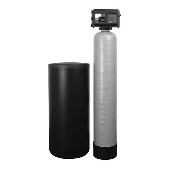
- Page 1 IRON SOFT PLUS ™ SERIES Water Conditioners Installation Instructions & Owner’s Manual...
- Page 2 CAUTION: The manufacturer does not recommend the use of any resin cleaners. Please refer to page 6 in this manual or the warning label on the back of the brine tank. TABLE OF CONTENTS Installation Instructions Page 3-4 Start-up Procedures Page 5-6 Programming the Iron Soft Plus Timer Page 6-8...
- Page 3 INSTALLATION INSTRUCTIONS Although the Iron Soft Plus Series Water Conditioner is shipped complete, some assembly may be required. 1. After unboxing the unit, please note that on most models the control valve is installed on the tank. If not, remove “split flange” from control valve adapter base, remove cardboard tank shim. Inspect “O” Ring on top of flange and grease with silicone provided.
- Page 4 2. Notice on the casting, the inlet and outlet TOP VIEW markings, make sure the incoming water is plumbed to the inlet and outlet is plumbed to service (Fig. 3). Your water softener must be installed with a bypass valve. If your conditioner is not equipped with one, make a provision in the plumbing system for a bypass to be installed.
- Page 5 START UP PROCEDURES FOR ELECTRONIC CONTROLLER • After installation is complete, rotate bypass handles to bypass mode (see “Valves Closed” in Fig.3). • Turn on water and check for leaks. • Fully open a cold water faucet — preferably a laundry sink or bathtub with no aerator. •...
- Page 6 ’ START UP PROCEDURES FOR ELECTRONIC CONTROLLER CONT CAUTION: Damage or destruction to the media may occur if salts containing additives are used with the Iron Soft Plus models. Most “solar” and/or “block” salts do not contain additives detrimental to this unit. If unsure, please check with manufacturer. Many “pellet”...
- Page 7 TIMER OPERATION Set Time of Day When the timer is In Service, push either the Set Up or Set Down button once to adjust the Time of Day by one digit. Push and hold to adjust by several digits. Manually Initiating a Regeneration 1.
- Page 8 PROGRAMMING THE ELECTRONIC CONTROLLER 1. Enter 3200NT Programming Mode Press and hold both the Set Up and Set Down buttons for five (5) seconds to enter Programming Mode. When the program mode is entered, the program light illuminates. 2. Set Feed Water Hardness The feed water hardness setting displays only if the Regeneration Type is set to Meter Immediate or Meter Delayed.
- Page 9 LIGHT ALARM OPERATION Light panel operation with audio alarm: On the right side of the control valve there are 3 lights — green, yellow and red. 1. The green light indicates the unit is in the service position delivering soft water. 2.
- Page 10 WATER CONDITIONER FLOW DIAGRAMS 3b. SLOW RINSE POSITION: 3a. BRINE RINSE POSITION: Chlorine generator is turned off, raw water enters Raw water enters control head flowing through control head and flows down through the Zeolite the injector, drawing brine from the brine tank. mineral, rinsing chlorine and brine to drain.
- Page 11 TROUBLESHOOTING GUIDE PROBLEM CAUSE CORRECTION A. assure permanent electrical service A. electrical service to unit has been (check fuse, plug, pull chain or interrupted switch) 1. Softener fails B. timer is defective B. replace timer to regenerate C. power failure C.
- Page 12 PROBLEM CAUSE CORRECTION 6. Iron in A. check backwash, brine draw and conditioned A. fouled mineral bed brine tank fill — increase frequency of regeneration water A. plugged drain line flow control A. clean flow control 7. Excessive B. brine valve failure B.
- Page 13 REPLACEMENT PARTS PLASTIC BYPASS ASSEMBLY Item No. Part No. Description FP9452K83 O-ring - 119 FP13255 Mounting clip FP13314 Screw, hex washer head, 8-18x5/8 FP18706 Yoke, plastic 1” NPT FP13708 Yoke, 3/4” brass FP13708-40 Yoke, 1” sweat FP13708-45 Yoke, 3/4” sweat FP18706-02 Yoke, 3/4”...
- Page 14 REPLACEMENT PARTS...
- Page 15 REPLACEMENT PARTS CONTROL VALVE ASSEMBLY Item No. Part No. Description Item No. Part No. Description FP19328 2510 valve body 1" FP12090 3.5 GPM DLFC button FP10757 End spacer FP12091 4.0 GPM DLFC button FP10545 Seal ring FP12092 5.0 GPM DLFC button FP11451 Spacer FP12408...
- Page 16 REPLACEMENT PARTS...
- Page 17 REPLACEMENT PARTS POWER HEAD ASSEMBLY Part No. Description FP40264 Back plate FP17967 Fitting, liquid tight FP17845-02 Pin, hinge FP10300 Screw FP41062 3200NT timer assembly FP60219-02 Cover assembly, black w/ clear window FP15742 Screw cover FP12576 Cam, drive STF518 FP10909 Pin, cam FP14923 Screw, switch FP10302...
- Page 18 REPLACEMENT PARTS CHLORINATOR BOARD ASSEMBLY Item No. Part No. Description FP40154-01 Harness, 2510 chlorinator FP42038 Bracket, circuit board, wtr rght WR00020LF Chlorinator circuit board WR00040 24V dual transformer WR00030CA Chlorine generator SAFETY FLOAT ASSEMBLY Item No. Part No. Description CH4650-01 474 safety elbow 3/8"...
- Page 20 & CAPACITY PHYSICAL SPECIFICATIONS MODEL ISP1-1044 ISP1-1054 ISP1-1354 ISP2-1044 ISP2-1054 ISP2-1354 Capacity: Maximum 11,800 @ 12.4 22,600 @ 15.9 36,900 @ 21.2 20,300 @ 12.4 34,800@ 15.9 60,300 @ 26.5 (Grains/Lbs. NaCI) Medium 11,400 @ 9.3 20,700 @ 12.4 33,600 @ 15.9 19,100 @ 9.3...
Need help?
Do you have a question about the ISP1-1044 and is the answer not in the manual?
Questions and answers