Table of Contents
Advertisement
Quick Links
4
18/02/19
3
18/04/16
2
31/07/12
1
25/06/10
0
05/05/99
Rev.
Date
HLA – Double acting- hydraulic linear actuator
Use and maintenance manual
DOUBLE ACTING
HYDRAULIC LINEAR
Use and maintenance manual
Updated data-plate
Updated applicable
regulation (chapter 1.1.1)
General update
General update
Document release
Description
© Copyright by BIFFI Italia. All right reserved.
Contents may change without notice
HLA
ACTUATOR
MAN 646
Sassi
Ermanni
Ermanni
Ermanni
Lazzarini
Prepared
Orefici
Vigliano
Orefici
Vigliano
Stoto
Vigliano
Stoto
Vigliano
Aliani
Ziveri
Checked
Approved
Pag. 1
Advertisement
Table of Contents

Related Manuals for BIFFI HLA Series


Summary of Contents for BIFFI HLA Series
- Page 1 (chapter 1.1.1) Ermanni Stoto Vigliano 31/07/12 General update Ermanni Stoto Vigliano 25/06/10 General update Lazzarini Aliani Ziveri 05/05/99 Document release Rev. Date Description Prepared Checked Approved © Copyright by BIFFI Italia. All right reserved. Pag. 1 Contents may change without notice...
-
Page 2: Table Of Contents
7 Layouts ................35 7.1 Spare parts order ..............35 7.2 parts-list for maintenance and replacing procedure ....36 8 Date report for maintenance operations ......44 © Copyright by BIFFI Italia. All right reserved. Pag. 2 Contents may change without notice... - Page 3 The information contained is of exclusive reserved ownership of BIFFI Italia S.r.l and may be modified without prior notice. All rights reserved. © Copyright by BIFFI Italia. All right reserved.
-
Page 4: General Warnings
2014/34/EU: Directive and safety instructions for use in hazardous area 1.1.2 Terms and conditions Biffi Italia srl guarantees that all the items produced are free of defects in workmanship and manufacturing materials and meet relevant current specifications, provided they are installed, used and serviced according to the instructions contained in the present manual. -
Page 5: Identification Plate
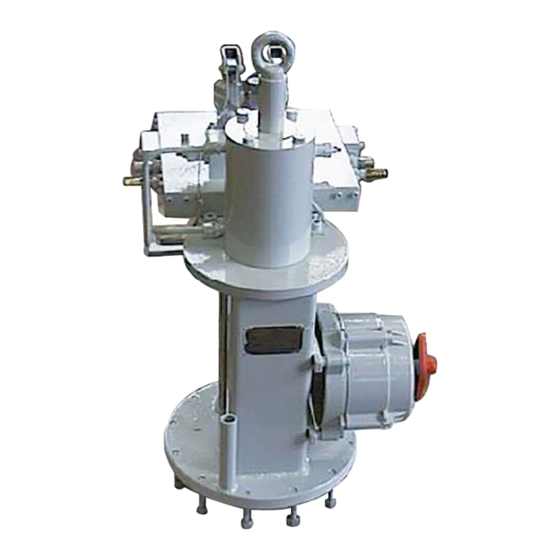
The actuator pedestal has a flange with threaded holes to fix the actuator to the valve. © Copyright by BIFFI Italia. All right reserved. Pag. 5 Contents may change without notice... - Page 6 HLA – Double acting- hydraulic linear actuator Use and maintenance manual BIFFI can supply different types of control system following Customer’s requirements. The expected lifetime of actuator is approximately 25 years . Lifting eyelets Manual Hand-Pump MHP (optional) Hydraulic cylinder...
-
Page 7: Data Sheet
The actuator should be handled with appropriate lifting means. The weight of the actuator is reported on the delivery bill. Picture 1 – Lifting points for HLA actuators © Copyright by BIFFI Italia. All right reserved. Pag. 7 Contents may change without notice... - Page 8 2 = don’t lay the actuator on tie-rods of 1 = point of support - cylinder 3 = don’t lay the actuator on accessories ( manual hand-pump, hydraulic control system etc. ) © Copyright by BIFFI Italia. All right reserved. Pag. 8 Contents may change without notice...
-
Page 9: Storage
Installation, commissioning and maintenance and repair works should be carried out by qualified staff. A non-conforming assembly could be the source of serious accidents. © Copyright by BIFFI Italia. All right reserved. Pag. 9 Contents may change without notice... - Page 10 Note: the eyebolt is sized for the lifting of the only actuator (NOT ACTUATOR+VALVE). Proper lifting points have to be foreseen for the valve. © Copyright by BIFFI Italia. All right reserved. Pag. 10 Contents may change without notice...
- Page 11 Lubricate the valve stem with grease in order to make the assembly easier 2) To make easier the assembly, the valve stem has to be in perfect vertical position. © Copyright by BIFFI Italia. All right reserved. Pag. 11 Contents may change without notice...
- Page 12 The screwing values in Table 1 were calculated considering the materials ASTM A320 L7 for screws or tie rods and ASTM A194 gr.2H for the nuts. © Copyright by BIFFI Italia. All right reserved. Pag. 12 Contents may change without notice...
-
Page 13: Hydraulic Connections
Make the connections in compliance with applicable wiring diagrams ❑ on the documentation supplied. Screw the cable gland. ❑ Replace the plastic plugs of unused entries with metal plugs. ❑ © Copyright by BIFFI Italia. All right reserved. Pag. 13 Contents may change without notice... -
Page 14: Commissioning
) Make a complete functional test in order to verify all the operations ❑ are executed according to operating schematic diagram supplied. © Copyright by BIFFI Italia. All right reserved. Pag. 14 Contents may change without notice... -
Page 15: Operation And Use
The power and control systems are supplied on specific customer demand. For all the relevant information please refer to the specific documentation supplied. © Copyright by BIFFI Italia. All right reserved. Pag. 15 Contents may change without notice... -
Page 16: Residual Risks
105 bar the manual override is similar to chapter 7.2 table 3. For nominal pressure upper to 105 bar the manual override will be OMFB for carbon steel material, or dedicated model engineered by BIFFI for stainless steel material ©... - Page 17 HLA – Double acting- hydraulic linear actuator Use and maintenance manual 3.3.2 Remote control operations © Copyright by BIFFI Italia. All right reserved. Pag. 17 Contents may change without notice...
- Page 18 HLA – Double acting- hydraulic linear actuator Use and maintenance manual © Copyright by BIFFI Italia. All right reserved. Pag. 18 Contents may change without notice...
-
Page 19: Calibration Of The Linear Stroke
(fully open or closed valve), screw the stop screw by turning it clockwise until the valve reaches the right position. When the adjustment is over tighten the plug (t). ❑ © Copyright by BIFFI Italia. All right reserved. Pag. 19 Contents may change without notice... - Page 20 For high pressure cylinder models, the mechanical stop is internal (without protection cover) proceed at the same way : (1) remove the plug and (2) operate the adjusting screw © Copyright by BIFFI Italia. All right reserved. Pag. 20 Contents may change without notice...
-
Page 21: Calibration Of Microswitches (If Foreseen)
Check that the cover and the index show the proper position of ❑ the valve (Picture 9). Tighten the screws. ❑ Picture 7 – Micro-switches Picture 8 – Cam adjustment © Copyright by BIFFI Italia. All right reserved. Pag. 21 Contents may change without notice... - Page 22 Adjust the relative cams properly. Position indicator (index) Picture 9 – Position indicator and pin for micro-switches box © Copyright by BIFFI Italia. All right reserved. Pag. 22 Contents may change without notice...
-
Page 23: Calibration Of The Operation Time
For actuator models with control system it’s possible regulate the speed of actuator operations. The calibration of the operation time is made by Biffi Italia S.r.L according to customer requirements and to technical data-sheet included in technical documentation. If necessary it’s possible to modify or reset the operating time through... -
Page 24: Operational Tests And Inspections
To ensure the guaranteed SIL grade, according to IEC 61508, the functionality of actuator must be checked with regular intervals of time, as described in the Safety Manual © Copyright by BIFFI Italia. All right reserved. Pag. 24 Contents may change without notice... -
Page 25: Maintenance
© Copyright by BIFFI Italia. All right reserved. Pag. 25 Contents may change without notice... -
Page 26: Check And Restore Oil Level In The Manual Hand-Pump
Pour the new oil into the tank through the dipstick hole (1) on the ❑ cover (22). Replace the dipstick (1). ❑ Add oil (Table 2) if in the tank the level is BELOW MINIMUM Picture ❑ 13). © Copyright by BIFFI Italia. All right reserved. Pag. 26 Contents may change without notice... - Page 27 The cleanliness level for actuator without control-system is NAS 8 minimum. For actuator with control system the cleanliness level is that required by singles components, in any case Biffi Italia S.r.L respect the customer requirements to scope of supply, for applicable cleanliness level, refer to document:...
-
Page 28: Extraordinary Maintenance
For this operation is necessary to disassemble the closing plates (item 41 refer to table pag.34) from pedestal with coupling-joint. The following grease is used by BIFFI for standard working temperature and suggested for re-lubrication: © Copyright by BIFFI Italia. All right reserved. -
Page 29: Replacing The Seals Of The Cylinder
(6) surface, so as to be able to easily restore the setting of the actuator mechanical stop, once the maintenance procedures have been completed. © Copyright by BIFFI Italia. All right reserved. Pag. 29 Contents may change without notice... - Page 30 To replace the piston seal ring (18) proceed as follows : 1) Remove the existing Teflon seal ring (18) with its O-ring from their groove. © Copyright by BIFFI Italia. All right reserved. Pag. 30 Contents may change without notice...
- Page 31 7) Screw the plug (12) into the cylinder end flange. Carry out a few operations (Sect. 3) to check there are no leakages from the gaskets. © Copyright by BIFFI Italia. All right reserved. Pag. 31 Contents may change without notice...
- Page 32 HLA – Double acting- hydraulic linear actuator Use and maintenance manual DOUBLE ACTING HYDRAULIC LINEAR ACTUATOR SECTIONAL DRAWING © Copyright by BIFFI Italia. All right reserved. Pag. 32 Contents may change without notice...
-
Page 33: Dismantling And Demolition
(ex. metallic, and plastic materials, fluids etc.) and send them to differentiated waste collection sites, as provided for by the laws and provisions in force. © Copyright by BIFFI Italia. All right reserved. Pag. 33 Contents may change without notice... -
Page 34: Troubleshooting
Customer Service control group Incorrect position of Wrong adjustment of Reset (Par. 3.4) the valve mechanical stops Wrong warning of Reset (Par. 3.5) micro-switches © Copyright by BIFFI Italia. All right reserved. Pag. 34 Contents may change without notice... -
Page 35: Layouts
Use and maintenance manual 7 Layouts SPARE PARTS ORDER For spare parts order to the relevant BIFFI office please make reference to BIFFI order confirmation concerning all the supply, and serial number of the actuator (Sect. 1.2) for any specific spare part for a specific actuator model. -
Page 36: Parts-List For Maintenance And Replacing Procedure
HLA – Double acting- hydraulic linear actuator Use and maintenance manual 7.2 PARTS-LIST FOR MAINTENANCE AND REPLACING PROCEDURE Table 1: Pedestal with coupling joint © Copyright by BIFFI Italia. All right reserved. Pag. 36 Contents may change without notice... - Page 37 HLA – Double acting- hydraulic linear actuator Use and maintenance manual Table 2: hydraulic cylinder © Copyright by BIFFI Italia. All right reserved. Pag. 37 Contents may change without notice...
- Page 38 HLA – Double acting- hydraulic linear actuator Use and maintenance manual Table 3: Hydraulic control unit MHP © Copyright by BIFFI Italia. All right reserved. Pag. 38 Contents may change without notice...
- Page 39 HLA – Double acting- hydraulic linear actuator Use and maintenance manual © Copyright by BIFFI Italia. All right reserved. Pag. 39 Contents may change without notice...
- Page 40 HLA – Double acting- hydraulic linear actuator Use and maintenance manual © Copyright by BIFFI Italia. All right reserved. Pag. 40 Contents may change without notice...
-
Page 41: Date Report For Maintenance Operations
Next maintenance operation date: ……… exec. by : ………… ……… exec. by : ………… Start-up date : ( in factory, on delivery ).……………………. .……………………. ( on plant ) © Copyright by BIFFI Italia. All right reserved. Pag. 41 Contents may change without notice...
Need help?
Do you have a question about the HLA Series and is the answer not in the manual?
Questions and answers