Table of Contents
Advertisement
Quick Links
Biffi HLA
Double-Acting Hydraulic Linear Actuator
Copyright © Biffi. The information in this document is subject to change without notice. Updated data sheets can be obtained from our website www.biffi.it or from your nearest Biffi Center:
Biffi Italia s.r.l. - Strada Biffi 165, 29017 Fiorenzuola d'Arda (PC) – Italy PH: +39 0523 944 411 – biffi_italia@biffi.it
Installation, Operation and Maintenance Manual
MAN 646 Rev. 5
March 2022
Advertisement
Table of Contents

Subscribe to Our Youtube Channel
Related Manuals for BIFFI HLA


Summary of Contents for BIFFI HLA
- Page 1 Double-Acting Hydraulic Linear Actuator Copyright © Biffi. The information in this document is subject to change without notice. Updated data sheets can be obtained from our website www.biffi.it or from your nearest Biffi Center: Biffi Italia s.r.l. - Strada Biffi 165, 29017 Fiorenzuola d'Arda (PC) – Italy PH: +39 0523 944 411 – biffi_italia@biffi.it...
- Page 2 Revision Details Installation, Operation and Maintenance Manual March 2022 MAN 646 Rev. 5 Revision Details Rev. Date Description Prepared Checked Approved March 2022 General update (Migration to new template) February 2019 Updated data plate Sassi Orefici Vigliano April 2016 Updated applicable regulation (chapter 1.1.1) Ermanni Orefici Vigliano...
-
Page 3: Table Of Contents
3.3.2 Remote Control Operations ............14 Calibration of the Angular Stroke ..............16 Calibration of Microswitches (Biffi Limit Switch Box Only) ......19 Calibration of the Operation Time ............... 21 Section 4: Operational Tests and Inspections Operational Tests and Inspections ................. 22 Section 5: Maintenance Periodic Maintenance .................. - Page 4 Installation, Operation and Maintenance Manual Table of Contents March 2022 MAN 646 Rev. 5 Section 6: Troubleshooting Failure or Breakdown Research ..............31 Section 7: Layouts Spare Parts Order ..................32 Parts List for Maintenance and Replacing Procedure ........33 Section 8: Date Report for Maintenance Operations Date Report for Maintenance Operations ..............
-
Page 5: Section 1: General Warnings
1.1.2 Terms and Conditions Biffi Italia s.r.l. guarantees that all the items produced are free of defects in workmanship and manufacturing materials and meet relevant current specifications, provided they are installed, used and serviced according to the instructions contained in the present manual. -
Page 6: Identification Plate
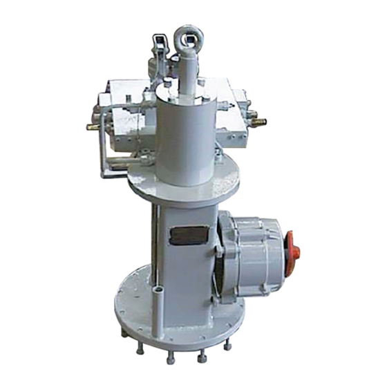
Figure 1 Data plate Introducing the Actuator HLA double-acting hydraulic linear actuators are suitable for the operation of linear valves (wedge gate valves, through conduit gate valves) for ON-OFF and modulating heavy-duty service. The actuator is made up of a hydraulic cylinder and a mounting pedestal complete with a joint for the coupling to the valve stem of actuator output stem. -
Page 7: Data Sheet
Installation, Operation and Maintenance Manual Section 1: General Warnings MAN 646 Rev. 5 March 2022 Figure 2 Identification of actuator parts Lifting eyelets Manual handpump MHP (optional) Hydraulic cylinder Valve position indicator Valve coupling 250 k Manual override Stroke (mm) Cylinder diameter (mm) Max. -
Page 8: Section 2: Installation
+ actuator assembly. Avoid that during the handling, the actuator passes above the staff. The actuator should be handled with appropriate lifting means. The weight of the actuator is reported on the delivery bill. Figure 3 Lifting points for HLA actuators 1 = Lifting points (obligatory) Installation... - Page 9 Installation, Operation and Maintenance Manual Section 2: Installation MAN 646 Rev. 5 March 2022 Figure 4 Positioning by chains 1 = point of support Figure 5 Positioning by slings WARNING 2 = don’t lay the actuator on tie rods of cylinder 3 = don’t lay the actuator on accessories (manual handpump, hydraulic control system, etc.) Installation...
-
Page 10: Storage
Section 2: Installation Installation, Operation and Maintenance Manual March 2022 MAN 646 Rev. 5 Storage If the actuator needs storage before installation, follow these steps: • Place it on a wood surface in order not to deteriorate the area of valve coupling. •... - Page 11 Installation, Operation and Maintenance Manual Section 2: Installation MAN 646 Rev. 5 March 2022 To assemble the actuator onto the valve by bracket with threaded joint, proceed as follows: Figure 6 Pedestal with threaded coupling joint Table 1. Parts list Item Description Stud bolt...
- Page 12 Section 2: Installation Installation, Operation and Maintenance Manual March 2022 MAN 646 Rev. 5 To assemble the actuator onto the valve by bracket with shell joint, perform the following operations: Figure 7 Pedestal with shell coupling joint Table 2. Parts list Item Description Stud bolt...
- Page 13 Installation, Operation and Maintenance Manual Section 2: Installation MAN 646 Rev. 5 March 2022 Check that the coupling dimensions of the valve flange and stem, or of the relevant extension, meet the actuator coupling dimensions (valve stem and flange). Lubricate the valve stem with grease in order to make the assembly easier. To make the assembly easier, the valve stem has to be in perfect vertical position.
-
Page 14: Hydraulic Connections
Section 2: Installation Installation, Operation and Maintenance Manual March 2022 MAN 646 Rev. 5 Hydraulic Connections WARNING Check that the values of hydraulic supply available are compatible with those reported on the identification plate of the actuator. NOTICE The connections should be made by qualified staff. Use pipes and connections appropriate as for type, material and dimensions. -
Page 15: Electrical Connections (If Any)
Installation, Operation and Maintenance Manual Section 2: Installation MAN 646 Rev. 5 March 2022 Electrical Connections (if Any) WARNING Use components appropriate as for type, material and dimensions. The connections should be made by qualified staff. Before carrying out any operation, cut line power off. Safety provisions as per CEI 64-8 regulation should be complied with (same as IEC 60364). -
Page 16: Section 3: Operation And Use
Section 3: Operation and Use Installation, Operation and Maintenance Manual March 2022 MAN 646 Rev. 5 Section 3: Operation and Use Operation Description The supply fluid pressurizes the hydraulic cylinder chamber relevant to the operation to carry out (opening or closing) (see following pages). This pressure starts the linear motion of the piston and the consequent motion of the valve stem that is coupled. -
Page 17: Residual Risks
WARNING Refer to applicable control schematic in supplied documentation. The HLA actuators can have an emergency manual override in addition to the local and/or remote control system which controls the oil supplied by a power pack for the “normal” actuator operation. -
Page 18: Remote Control Operations
Section 3: Operation and Use Installation, Operation and Maintenance Manual March 2022 MAN 646 Rev. 5 3.3.2 Remote Control Operations Figure 10 Example of control schematics for double-acting HLA actuator TEST/RE-CHARGE POINT CONNECTIONS AT CUSTOMER CARE OIL SUPPLY LINE OIL RETURN LINE E.M. - Page 19 Installation, Operation and Maintenance Manual Section 3: Operation and Use MAN 646 Rev. 5 March 2022 Figure 11 Example of control schematics for double-acting HLA actuator with power pack ELECTRIC CONNECTION OF SET SIGNAL (4-20 mA) ELECTRIC CONNECTIONS OF POWER SUPPLY (220 V 60 Hz)
-
Page 20: Calibration Of The Angular Stroke
Section 3: Operation and Use Installation, Operation and Maintenance Manual March 2022 MAN 646 Rev. 5 Calibration of the Angular Stroke It is important that the mechanical stops of the actuator (and not those of the valve) stop the linear stroke at both extreme valve position (fully open and fully closed), except when this is required by the valve operation. - Page 21 Installation, Operation and Maintenance Manual Section 3: Operation and Use MAN 646 Rev. 5 March 2022 For the adjustment of the mechanical stop on the end flange of cylinder, follow these steps (Figure 13): • Remove the plug (t) with the specific wrench (c1). •...
- Page 22 Section 3: Operation and Use Installation, Operation and Maintenance Manual March 2022 MAN 646 Rev. 5 For high pressure cylinder models, the mechanical stop is internal (without protection cover). Proceed at the same way: (1) remove the plug and (2) operate the adjusting screw. Figure 14 Operation and Use...
-
Page 23: Calibration Of Microswitches (Biffi Limit Switch Box Only)
Section 3: Operation and Use MAN 646 Rev. 5 March 2022 Calibration of Microswitches (Biffi Limit Switch Box Only) NOTICE Operate only the microswitch corresponding to the direction of operation being carried out, as clearly reported on the microswitch. WARNING If different microswitches assembly or limit switch box is supplied, please refer to the specific documentation. - Page 24 Section 3: Operation and Use Installation, Operation and Maintenance Manual March 2022 MAN 646 Rev. 5 Figure 16 Cam adjustment If the index (Figure 17) does not signal the proper position of the valve but is turned by 90°: • Remove the roll pin placed on the position indicator (index).
-
Page 25: Calibration Of The Operation Time
For actuator models with control system, it’s possible to regulate the speed of actuator operations. The calibration of the operation time is made by Biffi Italia s.r.l. according to customer requirements and to technical data sheet included in technical documentation. -
Page 26: Section 4: Operational Tests And Inspections
Section 4: Operational Tests and Inspections Installation, Operation and Maintenance Manual March 2022 MAN 646 Rev. 5 Section 4: Operational Tests and Inspections NOTICE To ensure the guaranteed SIL grade, according to IEC 61508, the functionality of actuator must be checked with regular intervals of time, as described in the Safety Manual. Operational Tests and Inspections... -
Page 27: Section 5: Maintenance
Installation, commissioning and maintenance and repair works should be carried out by qualified staff. Periodic Maintenance HLA actuators are designed to operate long-term in heavy-duty operating conditions without maintenance needs. NOTICE Periodicity and regularity of inspections is particularly influenced by specific environmental and working conditions. -
Page 28: Check And Restore Oil Level In The Hydraulic Manual Handpump
NAS 8 minimum. For actuator with control system, the cleanliness level is that required by single components. In any case, Biffi Italia s.r.l. respects the customer requirements to scope of supply. For applicable cleanliness level, refer to document: technical data sheet for actuators. - Page 29 Installation, Operation and Maintenance Manual Section 5: Maintenance MAN 646 Rev. 5 March 2022 Table 6. Features of hydraulic oil suggested by Biffi Italia s.r.l. for refilling in different working conditions Standard temperature conditions (-30 °C/+85 °C): Producer AGIP Name ARNICA 22 Viscosity at 40 °C...
-
Page 30: Extraordinary Maintenance
5.2.1 Lubrication of Mechanism For normal duty, the HLA actuator is lubricated "for life". In case of high load and high frequency of operation, it may be necessary to periodically restore the lubrication; it is advisable to apply a generous coating of grease on the contact surfaces of moving parts. -
Page 31: Replacement Of Cylinder Seals
Installation, Operation and Maintenance Manual Section 5: Maintenance MAN 646 Rev. 5 March 2022 5.2.2 Replacement of Cylinder Seals (refer to Figure 20) WARNING Before carrying out any maintenance operation, it is necessary to close the hydraulic feed line and exhaust the pressure from the actuator cylinder and from the control unit to ensure safety of maintenance staff. - Page 32 Section 5: Maintenance Installation, Operation and Maintenance Manual March 2022 MAN 646 Rev. 5 To replace the piston seal ring (8), proceed as follows : Remove the existing Teflon seal ring (8) with its O-ring from their groove. Clean the groove carefully and lubricate it with a protective oil or grease film. Assemble the new O-ring into its groove and lubricate it with a protective oil or grease film.
- Page 33 Installation, Operation and Maintenance Manual Section 5: Maintenance MAN 646 Rev. 5 March 2022 Figure 20 Double-acting hydraulic linear actuator sectional drawing Table 8. Parts list Item Description Item Description Piston Eyebolt Piston seal ring Stop setting screw Piston rod Back-up ring Piston rod bushing Piston rod seal ring...
-
Page 34: Dismantling And Demolition
Section 5: Maintenance Installation, Operation and Maintenance Manual March 2022 MAN 646 Rev. 5 Dismantling and Demolition Before starting the disassembly, a large area should be created around the actuator so as to allow any kind of movement without problems of further risks created by worksite. WARNING Before disassembling the actuator, it is necessary to close the pneumatic feed line and discharge pressure from the cylinder of the actuator from the control unit and from the... -
Page 35: Section 6: Troubleshooting
Repair or replace Wrong position of the distributor of the hydraulic Restore correct position Actuator does not work manual override Call Biffi Italia s.r.l. Failure of the control system Customer Service Clean or replace the Clogged filter cartridge Low supply pressure Restore (Section 1.4) -
Page 36: Section 7: Layouts
Section 7: Layouts Spare Parts Order For spare parts order to the relevant Biffi office, please make reference to Biffi order confirmation concerning all the supply and serial number of the actuator (Section 1.2) for any specific spare part for a specific actuator model. -
Page 37: Parts List For Maintenance And Replacing Procedure
Installation, Operation and Maintenance Manual Section 7: Layouts March 2022 MAN 646 Rev. 5 Parts List for Maintenance and Replacing Procedure Figure 21 Pedestal with coupling joint Table 10. Parts list Item Description Material Pedestal Carbon steel Scraper ring flange Stainless steel Shell joint Alloy steel... - Page 38 Section 7: Layouts Installation, Operation and Maintenance Manual March 2022 MAN 646 Rev. 5 Figure 22 Hydraulic cylinder Layouts...
- Page 39 Installation, Operation and Maintenance Manual Section 7: Layouts March 2022 MAN 646 Rev. 5 Table 11. Parts list Item Description Material Piston Carbon steel Stop setting screw Stainless steel Piston rod Stainless steel Piston rod bushing Steel + BZ + Teflon Head flange Carbon steel End flange...
- Page 40 Section 7: Layouts Installation, Operation and Maintenance Manual March 2022 MAN 646 Rev. 5 Figure 23 Hydraulic control unit MHP OIL TANK RELIEF VALVE RELIEF VALVE FOR AUTOMATIC OPERATION FLOW REGULATOR RELIEF VALVE FOR MANUAL OPERATION Layouts...
- Page 41 Installation, Operation and Maintenance Manual Section 7: Layouts March 2022 MAN 646 Rev. 5 Table 12. Parts list Item Description Material Dipstick Carbon steel + Aluminum Plug Carbon steel Washer Copper Hydraulic tank Carbon steel Handpump See Table 13 O-ring *Fluorosilicon rubber Ball Stainless steel...
- Page 42 Section 7: Layouts Installation, Operation and Maintenance Manual March 2022 MAN 646 Rev. 5 Figure 24 Hydraulic control unit handpump Table 13. Parts list Item Description Material Ball Stainless steel Delivery valve bush Carbon steel Suction valve bush Carbon steel Spring Stainless steel Suction valve seat...
-
Page 43: Section 8: Date Report For Maintenance Operations
Installation, Operation and Maintenance Manual Section 8: Date Report for Maintenance Operations MAN 646 Rev. 5 March 2022 Section 8: Date Report for Maintenance Operations Last maintenance operation date: (in factory, on delivery ): ……… exec. by : ………… ……… exec. by : ………… ………... - Page 44 VCIOM-17044-EN ©2022 Biffi. All rights reserved. Biffi Italia s.r.l. Strada Biffi 165 The contents of this publication are presented for information purposes only, 29017 Fiorenzuola d’Arda (PC) and while every effort has been made to ensure their accuracy, they are not...
Need help?
Do you have a question about the HLA and is the answer not in the manual?
Questions and answers