Table of Contents
Advertisement
Quick Links
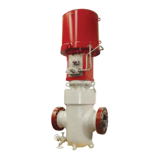
Biffi HLAS-C Compact Series
High Pressure Spring-Return Hydraulic Linear Actuator
Copyright © Biffi. The information in this document is subject to change without notice. Updated data sheets can be obtained from our website www.biffi.it or from your nearest Biffi Center:
Biffi Italia s.r.l. - Strada Biffi 165, 29017 Fiorenzuola d'Arda (PC) – Italy PH: +39 0523 944 411 – biffi_italia@biffi.it
Installation, Operation and Maintenance Manual
MAN 707 Rev. 3
March 2022
Advertisement
Table of Contents

Related Manuals for BIFFI HLAS-C Series


Summary of Contents for BIFFI HLAS-C Series
- Page 1 High Pressure Spring-Return Hydraulic Linear Actuator Copyright © Biffi. The information in this document is subject to change without notice. Updated data sheets can be obtained from our website www.biffi.it or from your nearest Biffi Center: Biffi Italia s.r.l. - Strada Biffi 165, 29017 Fiorenzuola d'Arda (PC) – Italy PH: +39 0523 944 411 – biffi_italia@biffi.it...
- Page 2 Revision Details Installation, Operation and Maintenance Manual March 2022 MAN 707 Rev. 3 Revision Details Rev. Date Description Prepared Checked Approved March 2022 General update (Migration to new template) May 2018 Updated applicable regulation (chapter 1.1.1) Ermanni Orefici Vigliano April 2016 Updated applicable regulation (chapter 1.1.1) Ermanni Orefici...
-
Page 3: Table Of Contents
3.3.2 Remote Control Operations (For Information Only) ......14 Calibration of the Angular Stroke ..............15 Calibration of Microswitches (*For Biffi Limit Switch Box) ......18 Calibration of the Operation Time .............. 21 Section 4: Operational Tests and Inspections Operational Tests and Inspections ................. 22 Section 5: Maintenance Periodic Maintenance ................. - Page 4 Table of Contents Installation, Operation and Maintenance Manual March 2022 MAN 707 Rev. 3 Section 6: Troubleshooting Failure or Breakdown Research ..............30 Section 7: Layouts Spare Parts Order ..................31 Parts List for Maintenance and Replacing Procedure ........32 Section 8: Date Report for Maintenance Operations Date Report for Maintenance Operations ..............
-
Page 5: Section 1: General Warnings
1.1.2 Terms and Conditions Biffi Italia s.r.l. guarantees that all the items produced are free of defects in workmanship and manufacturing materials and meet relevant current specifications, provided they are installed, used and serviced according to the instructions contained in the present manual. -
Page 6: Identification Plate
The actuator pedestal has a flange with threaded holes to fix the actuator to the valve. Biffi can supply different types of control system following customer’s requirements. -
Page 7: Data Sheet
Installation, Operation and Maintenance Manual Section 1: General Warnings MAN 707 Rev. 3 March 2022 Figure 2 Identification of actuator parts Hydraulic cylinder Spring cartridge Valve position indicator Valve coupling Valve position visual indicator Lifting eyelet Lifting eyelets suitable for vertical suitable for transport horizontal transport... -
Page 8: Section 2: Installation
Installation, Operation and Maintenance Manual Section 2: Installation March 2022 MAN 707 Rev. 3 Section 2: Installation Checks upon Actuator Receipt • Check that the model, the serial number of the actuator and the technical data reported on the identification plate correspond with those of order confirmation (Section 1.2). - Page 9 MHP body); remove the blind plug and restore the dipstick before operating the actuator with MHP. Biffi hydraulic manual handpump must be maintained with tank under the handpump to operate the actuator with MHP properly.
-
Page 10: Storage
Installation, Operation and Maintenance Manual Section 2: Installation March 2022 MAN 707 Rev. 3 Storage If the actuator needs storage before installation, follow these steps: • Place it on a wood surface in order not to deteriorate the area of valve coupling. •... - Page 11 Installation, Operation and Maintenance Manual Section 2: Installation March 2022 MAN 707 Rev. 3 To assemble the actuator onto the valve by bracket with threaded joint, proceed as follows: Figure 5 Pedestal with threaded coupling joint Table 1. Parts list Item Description Stud bolt...
- Page 12 Installation, Operation and Maintenance Manual Section 2: Installation March 2022 MAN 707 Rev. 3 To assemble the actuator onto the valve by bracket with shell joint, perform the following operations: Figure 6 Pedestal with shell coupling joint Table 2. Parts list Item Description Stud bolt...
- Page 13 Installation, Operation and Maintenance Manual Section 2: Installation March 2022 MAN 707 Rev. 3 Check that the coupling dimensions of the valve flange and stem, or of the relevant extension, meet the actuator coupling dimensions (valve stem and flange). Lubricate the valve stem with grease in order to make the assembly easier. To make the assembly easier, the valve stem has to be in perfect vertical position.
-
Page 14: Hydraulic Connections
Installation, Operation and Maintenance Manual Section 2: Installation March 2022 MAN 707 Rev. 3 Hydraulic Connections WARNING Check that the values of hydraulic supply available are compatible with those reported on the identification plate of the actuator. NOTICE The connections should be made by qualified staff. Use pipes and connections appropriate as for type, material and dimensions. -
Page 15: Commissioning
Installation, Operation and Maintenance Manual Section 2: Installation March 2022 MAN 707 Rev. 3 Commissioning WARNING Installation, commissioning and maintenance and repair works should be made by qualified staff. Upon actuator commissioning, please carry out the following checks: • Check that paint is not damaged during transport. If necessary, repair the damages to paint coat. -
Page 16: Section 3: Operation And Use
Section 3: Operation and Use Installation, Operation and Maintenance Manual March 2022 MAN 707 Rev. 3 Section 3: Operation and Use Operation Description The supply fluid pressurizes the hydraulic cylinder chamber relevant to the operation to carry out (opening or closing) (see following pages). This pressure starts the linear motion of the piston and the consequent motion of the valve stem that is coupled. -
Page 17: Residual Risks
“Normal operation” with oil supply from a power pack, or the “Emergency manual operation”. The manual override will be OMFB for carbon steel material or dedicated model engineered by Biffi for stainless steel material. -
Page 18: Remote Control Operations (For Information Only)
Section 3: Operation and Use Installation, Operation and Maintenance Manual March 2022 MAN 707 Rev. 3 3.3.2 Remote Control Operations (For Information Only) Figure 8 TUBING BETWEEN CABINET AND ACTUATOR BY OTHERS OIL SUPPLY LINE FITTINGS FOR 16 mm FITTINGS FOR 16 mm O.D. -
Page 19: Calibration Of The Angular Stroke
Installation, Operation and Maintenance Manual Section 3: Operation and Use MAN 707 Rev. 3 March 2022 Calibration of the Angular Stroke It is important that the mechanical stops of the actuator (and not those of the valve) stop the linear stroke at both extreme valve position (fully open and fully closed), except when this is required by the valve operation. - Page 20 Section 3: Operation and Use Installation, Operation and Maintenance Manual March 2022 MAN 707 Rev. 3 For the adjustment of the mechanical stop on the end flange of cylinder, follow these steps (see following figure and refer to Section 7.2, Figure 24 for items reference): •...
- Page 21 Installation, Operation and Maintenance Manual Section 3: Operation and Use MAN 707 Rev. 3 March 2022 For the adjustment of linear stroke in the lower position, operate the two regulation rings (see Section 7.2, Figure 25, item 10). To increase the linear stroke, unscrew the regulation rings from threaded surface of stem valve joint (see Section 7.2, Figure 25, item 8).
-
Page 22: Calibration Of Microswitches (*For Biffi Limit Switch Box)
Installation, Operation and Maintenance Manual March 2022 MAN 707 Rev. 3 Calibration of Microswitches (*For Biffi Limit Switch Box) WARNING *For information only: If different microswitches assembly or limit switch box is supplied, please refer to the specific documentation. NOTICE Operate only the microswitch corresponding to the direction of operation being carried out, as clearly reported on the microswitch. - Page 23 Installation, Operation and Maintenance Manual Section 3: Operation and Use MAN 707 Rev. 3 March 2022 Figure 15 Microswitches box Figure 16 Cam adjustment If the index (Figure 17) does not signal the proper position of the valve but is turned by 90°: •...
- Page 24 Figure 17 Position indicator and pin for microswitches box Position indicator (index) Figure 18 Transmission device for non-Biffi limit-switch box NOTICE (Refer for information only to Section 7.2, Figure 26 and prior to technical documentation furnished with actuators.) Operation and Use...
-
Page 25: Calibration Of The Operation Time
For actuator models equipped with control system, it’s possible to regulate the speed of actuator operations. The calibration of the operation time is made by Biffi Italia s.r.l. according to customer requirements and to technical data sheet included in technical documentation. -
Page 26: Section 4: Operational Tests And Inspections
Section 4: Operational Tests and Inspections Installation, Operation and Maintenance Manual March 2022 MAN 707 Rev. 3 Section 4: Operational Tests and Inspections NOTICE To ensure the guaranteed SIL grade, according to IEC 61508, the functionality of actuator must be checked with regular intervals of time, as described in the Safety Manual. Operational Tests and Inspections... -
Page 27: Section 5: Maintenance
Installation, Operation and Maintenance Manual Section 5: Maintenance MAN 707 Rev. 3 March 2022 Section 5: Maintenance NOTICE Before carrying out any maintenance operation, it is necessary to close the hydraulic feed line and exhaust the pressure from the actuator cylinder and from the control unit to ensure safety of maintenance staff. - Page 28 The cleanliness level for actuator without control system is generally NAS 8 minimum. For actuator with control system, the cleanliness level is that required by single components. In any case, Biffi Italia s.r.l. respects the customer requirements to scope of supply. For applicable cleanliness level, refer to document: technical data sheet for actuators.
-
Page 29: Extraordinary Maintenance
Installation, Operation and Maintenance Manual Section 5: Maintenance MAN 707 Rev. 3 March 2022 HLAS-C does not need lubrication during its life. However, it’s possible to utilize the following grease during special maintenance operations, for example, to lubricate the spring's surface inside spring cartridge. Table 6. - Page 30 Section 5: Maintenance Installation, Operation and Maintenance Manual March 2022 MAN 707 Rev. 3 Figure 20 Unscrew the fixing screws and washers (see items 14-15, Figure 23, Section 7.2). Lift the spring module with hook for chain as explained in Section 2.2. Unscrew the screws (see item 22, Figure 25, Section 7.2) to disassemble the pedestal from the base of hydraulic cylinder.
- Page 31 Installation, Operation and Maintenance Manual Section 5: Maintenance MAN 707 Rev. 3 March 2022 Seals Replacement Prior to reassembly, check that the actuator components are in good condition and are clean. Lubricate all the surfaces of the parts which move in contact with other components, by a recommended grease.
- Page 32 Section 5: Maintenance Installation, Operation and Maintenance Manual March 2022 MAN 707 Rev. 3 Reassembly Assemble the head flange (31, Figure 22) with the assembly piston and cylinder tube. Lubricate the upper and lower piston rod (1-2, Figure 22) surfaces with a protective oil or grease film and introduce it into the head flange hole, taking care not to damage the O-ring (3).
-
Page 33: Dismantling And Demolition
Installation, Operation and Maintenance Manual Section 5: Maintenance MAN 707 Rev. 3 March 2022 Dismantling and Demolition WARNING Before disassembling the actuator, it is necessary to intercept the hydraulic supply line and discharge pressure from the cylinder of the actuator from the control unit and from the accumulation tank, if present. -
Page 34: Section 6: Troubleshooting
Repair or replace Wrong position of the distributor of the hydraulic Restore correct position manual override Actuator does not work Call Biffi Italia s.r.l. Failure of the spring Customer Service Call Biffi Italia s.r.l. Failure of the control system Customer Service... -
Page 35: Section 7: Layouts
Section 7: Layouts Spare Parts Order For spare parts order to the relevant Biffi office, please make reference to Biffi order confirmation concerning all the supply and serial number of the actuator (Section 1.2) for any specific spare part for a specific actuator model. -
Page 36: Parts List For Maintenance And Replacing Procedure
Section 7: Layouts Installation, Operation and Maintenance Manual March 2022 MAN 707 Rev. 3 Parts List for Maintenance and Replacing Procedure Figure 22 Hydraulic cylinder Layouts... - Page 37 Installation, Operation and Maintenance Manual Section 7: Layouts March 2022 MAN 707 Rev. 3 Table 9. Parts list Item Description Material Upper stem Stainless steel Lower stem Alloy steel Anti-extrusion ring Stainless steel Lower seal flange Carbon steel Upper seal flange Carbon steel Piston Carbon steel...
- Page 38 Section 7: Layouts Installation, Operation and Maintenance Manual March 2022 MAN 707 Rev. 3 Figure 23 Spring cartridge Table 10. Parts list Item Description Material Lifting eyelet Carbon steel Head flange Carbon steel End flange Carbon steel Upper spring flange Carbon steel Lower spring flange Carbon steel...
- Page 39 Installation, Operation and Maintenance Manual Section 7: Layouts March 2022 MAN 707 Rev. 3 Figure 24 Kit stop setting screw Table 11. Parts list Item Description Material Gasket *SBR cellulose fillers Stop setting screw flange Carbon steel Stop setting screw Stainless steel Nylon Screw...
- Page 40 Section 7: Layouts Installation, Operation and Maintenance Manual March 2022 MAN 707 Rev. 3 Figure 25 Pedestal with coupling joint Table 12. Parts list Item Description Material Actuating ring Stainless steel Antirotation bar Stainless steel Closing plate Polycarbonate Closing plate gasket *NBR rubber Pedestal Stainless steel...
- Page 41 Installation, Operation and Maintenance Manual Section 7: Layouts March 2022 MAN 707 Rev. 3 Figure 26 Mounting kit for electric limit switches enclosure Table 13. Parts list Item Description Material Telescopic joint Limit switches box joint Stainless steel Limit switches box gasket *NBR rubber Setting plate Stainless steel...
-
Page 42: Section 8: Date Report For Maintenance Operations
Section 8: Date Report for Maintenance Operations Installation, Operation and Maintenance Manual March 2022 MAN 707 Rev. 3 Section 8: Date Report for Maintenance Operations Last maintenance operation date: (in factory, on delivery ): ……… exec. by : ………… ……… exec. by : ………… ………... - Page 43 Installation, Operation and Maintenance Manual Notes MAN 707 Rev. 3 March 2022 This page is intentionally left blank...
- Page 44 VCIOM-17050-EN ©2022 Biffi. All rights reserved. Biffi Italia s.r.l. Strada Biffi 165 The contents of this publication are presented for information purposes only, 29017 Fiorenzuola d’Arda (PC) and while every effort has been made to ensure their accuracy, they are not...
Need help?
Do you have a question about the HLAS-C Series and is the answer not in the manual?
Questions and answers