
Subscribe to Our Youtube Channel
Related Manuals for dallmeier DF4910HD-DN


Summary of Contents for dallmeier DF4910HD-DN
- Page 1 Installation and Configuration English High-Definition IP Network Cameras DF4910HD-DN DDF4910HDV-DN-IM/-SM Rev. 1.0.4 / 2013-09-09...
- Page 2 Third-party trademarks are named for information purposes only. Dallmeier electronic respects the intellectual property of third parties and always attempts to ensure the complete identification of third- party trademarks and indication of the respective holder of rights. In case that protected rights are not indicated separately, this circum- stance is no reason to assume that the respective trademark is unprotected.
-
Page 3: Table Of Contents
DF4910HD-DN | DDF4910HDV-DN-IM/-SM Table of Contents Introduction ....................6 Validity ......................6 Documents ......................6 Typographical Conventions................7 Safety Instructions..................8 General Notes....................10 Scope of Delivery ..................10 Transportation and Packaging ..............10 Warranty .......................10 Approvals/Certifications ................10 Appropriate Use ....................11 Performance Features ..................12 Requirements ....................13 General ......................13 Power Supply ....................13... - Page 4 DF4910HD-DN | DDF4910HDV-DN-IM/-SM Basic Settings .....................36 Language ......................36 System Time ....................36 8.2.1 Manual Configuration ..................37 8.2.2 Time Server ....................37 Camera Name....................38 User Management ..................38 8.4.1 Login Mode ....................38 8.4.1.1 Group Login ....................39 8.4.1.2 User Login.....................40 8.4.1.3 LDAP Login ....................41 8.4.2 Rights ......................44...
- Page 5 DF4910HD-DN | DDF4910HDV-DN-IM/-SM Interfaces .....................83 12.1 Data Display....................83 12.1.1 Filter ......................83 12.1.2 Position ......................84 Digital Image Shift..................86 Service and Info ..................88 14.1 Downloads ....................88 14.2 Factory Settings ....................88 14.3 Licenses ......................89 14.4 Event Log ......................89 14.5 Configuration File ..................90 14.5.1 Download ......................90...
-
Page 6: Introduction
DF4910HD-DN | DDF4910HDV-DN-IM/-SM Introduction Validity This document applies to the following devices: • DF4910HD-DN (IP network box camera, 5-megapixel, 1080p/30, Day/Night) • DDF4910HDV-DN-IM (IP network dome camera, in-ceiling mount variant, 5-megapixel, 1080p/30, Day/Night) • DDF4910HDV-DN-SM (IP network dome camera, surface mount variant, 5-megapixel, 1080p/30, Day/Night) The descriptions in this document are based on the software version 6.1.2.4 and apply to... -
Page 7: Typographical Conventions
DF4910HD-DN | DDF4910HDV-DN-IM/-SM Typographical Conventions This document may contain various warning words and symbols that indicate potential sources of danger. DANGER DANGER indicates a hazardous situation which, if not avoided, will result in death or serious injury. WARNING WARNING indicates a hazardous situation which, if not avoided, could result in death or serious injury. -
Page 8: Safety Instructions
System Components Only use internal components that have been tested and approved by Dallmeier. Inappropriate internal components may cause malfunctions, damages and data loss and may result in the loss of warranty. - Page 9 DF4910HD-DN | DDF4910HDV-DN-IM/-SM Lightning Storms To avoid damage to the units by electrical surge during lightning storms, unplug the units from the mains power supply (pull out the power plug). This is also recommended, when the units have been unused for a long period of time.
-
Page 10: General Notes
Certain functions and features may require the purchase of an additional license. Transportation and Packaging Store the original packaging for transportation at a later date. Dallmeier is not responsible for any damage resulting from unprofessional/improper trans- portation. The goods should only be shipped in their original packaging. -
Page 11: Appropriate Use
DF4910HD-DN | DDF4910HDV-DN-IM/-SM Appropriate use DF4910HD-DN The DF4910HD-DN is a 5-megapixel Full High-Definition (1080p/30) IP network box cam- era with automatic Day/Night operation supported by integrated ambient light sensing and a removable IR cut filter. It is designed for indoor installations on ceiling/wall brackets and can be powered via PoE (Power over Ethernet Class 0, IEEE 802.3af) or supplied with 12 V DC (separate power... -
Page 12: Performance Features
DF4910HD-DN | DDF4910HDV-DN-IM/-SM Performance Features The following list of features is valid for all devices described in this document: • 1/2.5" 5-megapixel CMOS image sensor with Dallmeier technology • Pure Digital Signal Processing • Real-time HD video • Automatic Day/Night switching using ambient light sensing and ICR... -
Page 13: Requirements
DF4910HD-DN | DDF4910HDV-DN-IM/-SM Requirements General Unfavourable local conditions may shorten the life of the products and may cause mal- functions or damages. Do not install/operate the devices in places • with a large amount of dust and dirt, • with steam or oil vapours (e.g. kitchen), •... -
Page 14: Outdoor Use
4.5.1 Box Camera DF4910HD-DN The box camera DF4910HD-DN is designed for indoor use. For outdoor use, the camera must always be installed in a proper weather-proof housing. However, note that direct sunlight can cause very high temperatures inside the housing. -
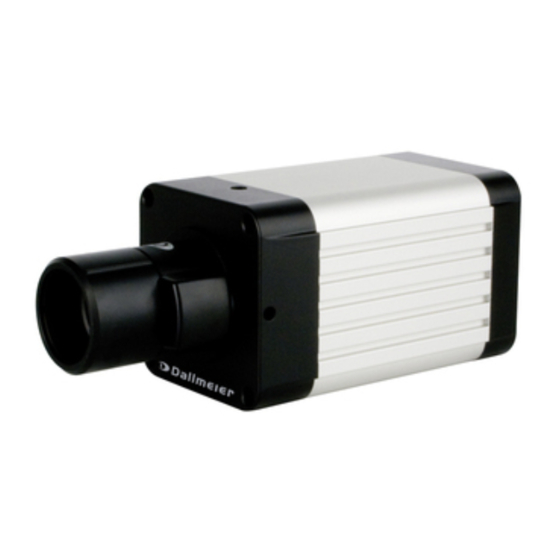
Page 15: Views And Connection Assignment
DF4910HD-DN | DDF4910HDV-DN-IM/-SM Views and Connection Assignment Box Camera ¼" tripod socket (on top and bottom side) for camera mounting Ambient light sensor Locking screw (focal length) CS lens mount Locking screw DC auto iris lens (focus) Fig. 5-1 The lens shown in Fig. 5-1 is illustrative only and may differ from the actual product. - Page 16 DF4910HD-DN | DDF4910HDV-DN-IM/-SM Video preview output DC auto iris interface (BNC, CVBS) for iris control Audio OUT / Micro IN (3.5 mm phone jack) Power IN (12 V DC) LAN / PoE SDHC LAN LED Power LED Weidmüller male connector...
-
Page 17: Dome Cameras
DF4910HD-DN | DDF4910HDV-DN-IM/-SM Dome Cameras 5.2.1 In-ceiling Mount Variant (IM) PG16 cable gland M6 screw eye bolt Ceiling clamp Housing Ambient light sensor 3-axis mount (pan / tilt / rotation) Removable foam ring Lens Trim ring with bubble Housing screw... - Page 18 DF4910HD-DN | DDF4910HDV-DN-IM/-SM Thread for PG16 cable gland M4 locking screw Thread for (ceiling clamp) housing screw Flexible cable fastener Flexible cable fastener Locking screw Locking screw (focus) (focal length) Video preview output Thread for (BNC, CVBS) housing screw Removable foam ring...
-
Page 19: Surface Mount Variant (Sm)
DF4910HD-DN | DDF4910HDV-DN-IM/-SM 5.2.2 Surface Mount Variant (SM) Mounting hole for Ø 4 mm screw Housing base Thread for PG16 cable gland 3-axis mount (pan / tilt / rotation) Ambient light sensor Removable foam ring Lens Housing with bubble Black inner... - Page 20 DF4910HD-DN | DDF4910HDV-DN-IM/-SM Thread for PG16 cable gland Mounting hole for Ø 4 mm screw Flexible cable fastener Flexible cable fastener Thread for Thread for housing screw housing screw Locking screw (focal length) Mounting hole for Video preview output Ø 4 mm screw...
-
Page 21: Camera Module
DF4910HD-DN | DDF4910HDV-DN-IM/-SM 5.2.3 Camera Module Removable foam ring Ambient light sensor Knurled screw (rotation, z-axis) 3-axis mount (pan / tilt / rotation) DC auto iris interface for iris control Flexible cable fastener Audio OUT / Microphone IN SDHC card... -
Page 22: Installation And Commissioning
DF4910HD-DN | DDF4910HDV-DN-IM/-SM Installation and Commissioning Box Camera The installation and commissioning of the unit may only be carried out by qualified per- sonnel. WARNING Electric shock hazard Danger of death or serious injury Always disconnect the PoE switch or the separate power supply unit from the mains socket (pull out the power plug) before connecting or disconnecting the device. -
Page 23: Installation And Commissioning
DF4910HD-DN | DDF4910HDV-DN-IM/-SM To attach the lens, proceed as follows: Remove the rear lens cap and the camera body cap. Carefully screw the lens into the CS lens mount (Fig. 5-1). If using a DC auto iris lens, connect the lens cable to the DC auto iris interface (Fig. -
Page 24: Back Focus
DF4910HD-DN | DDF4910HDV-DN-IM/-SM 6.1.3 Back Focus The back focus (focal flange length) is the distance between the rear lens element and the image sensor. Optimum focus is only possible if the correct distance is set. Generally, the back focus is optimized ex factory for all CS mount lenses offered by Dallmeier. -
Page 25: Dome Cameras
DF4910HD-DN | DDF4910HDV-DN-IM/-SM Dome Cameras The installation and commissioning of the units may only be carried out by qualified per- sonnel. WARNING Falling devices/objects or collapsing ceiling Danger of death or serious injury to the head Observe the manufacturer’s instructions about the maximum adequate carrying capacity of the supporting structure and the suspended ceiling or ceiling tiles. - Page 26 DF4910HD-DN | DDF4910HDV-DN-IM/-SM Step 1 Cut a circular recess (Ø 143 mm) into the suspended ceiling using a drywall utility saw or a jigsaw. Screw the M6 screw eye bolt onto the bottom side of the housing. Unscrew the 3 housing screws using a T20 torx wrench and remove the trim ring.
- Page 27 DF4910HD-DN | DDF4910HDV-DN-IM/-SM Step 2 Screw a ceiling hook on the supporting structure. Attach the safety wire to the M6 screw eye bolt (use a carabiner) and the ceiling hook. Run the required cables suspended from the ceiling through a PG16 cable gland.
- Page 28 DF4910HD-DN | DDF4910HDV-DN-IM/-SM Step 3 Tighten the M4 locking screw (Fig. 5-4) of both ceiling clamps with a Phillips screw- driver until the housing is fixed (Fig. 6-5). Ceiling clamp Ceiling clamp Suspended ceiling Phillips screwdriver Fig. 6-4 Locked ceiling clamp...
-
Page 29: Surface Mount Variant (Sm)
DF4910HD-DN | DDF4910HDV-DN-IM/-SM Step 4 Connect the required cables to the connectors of the camera module (see Fig. 5-7 and chapter “Pin Assignment” on page 97). If necessary, connect a CVBS monitor to the video preview output (Fig. - Page 30 DF4910HD-DN | DDF4910HDV-DN-IM/-SM Unscrew the 3 housing screws (Fig. 5-5) using a T20 torx wrench and remove the housing. Mark the drill holes on the ceiling/wall using the 3 pre-drilled mounting holes of the housing base (Fig. 5-6) as a template.
-
Page 31: Connection And Login
• a more powerful PC is required if several devices are configured with live video display (and/or live audio output) simultaneously. • a DirectX compatible graphics card and the ActiveX-based Dallmeier control are not required for the configuration without live video display or live audio output. -
Page 32: Connection
DF4910HD-DN | DDF4910HDV-DN-IM/-SM Connection The factory default IP address of the device is 192.168.2.28. Ensure that the PC/web browser can establish a connection to the device via Ethernet. Start the web browser. Enter the IP address of the device into the address bar of the web browser. - Page 33 DF4910HD-DN | DDF4910HDV-DN-IM/-SM Note the explanations below. Hide the title bar (A) if required. Change the connection method (D) if required. Adjust the live video resolution (E) if required. Enable the live audio output (F) if required.
-
Page 34: Login
DF4910HD-DN | DDF4910HDV-DN-IM/-SM Login The graphical user interface of the configuration mode is displayed after the successful identification as authorized user. The factory default admin password is “3”. Notice Risk of misuse by unauthorized users! Change the factory default admin password as soon as possible. - Page 35 DF4910HD-DN | DDF4910HDV-DN-IM/-SM Fig. 7-3 Configuration mode A Hide/show title bar B Switch between live and configuration mode C IP address of the device D Log out of configuration mode E Disable/enable live video display F Live video G Configuration menu...
-
Page 36: Basic Settings
DF4910HD-DN | DDF4910HDV-DN-IM/-SM Basic Settings The basic settings and the user management are integrated in the common settings menu. Language The graphical user interface can be displayed in various languages. Open the User interface dialogue via common settings > User interface .. -
Page 37: Manual Configuration
DF4910HD-DN | DDF4910HDV-DN-IM/-SM 8.2.1 Manual Configuration Note that no manual configuration is possible if the UTC time server synchronization is enabled. Select the Date/time tab. Fig. 8-3 Set the Date. Set the time. Confirm with oK. -
Page 38: Camera Name
DF4910HD-DN | DDF4910HDV-DN-IM/-SM Camera Name The camera can be assigned a unique name which then is displayed in an external ap- plication (e.g. SMAVIA Viewing Client ) and can be inserted directly in the video. Open the camera name dialogue via common settings > camera name .. -
Page 39: Group Login
DF4910HD-DN | DDF4910HDV-DN-IM/-SM Open the Login options dialogue via common settings > User management > Login options ..Fig. 8-6 Set the Login mode. Note the following sections about the different login modes. Finally, confirm with oK. -
Page 40: User Login
DF4910HD-DN | DDF4910HDV-DN-IM/-SM Select the tab of the relevant group. Enter a new Group name if required. Enter a New password. Repeat the new password in the Confirm password field. Finally, confirm with Apply. 8.4.1.2 user Login In the “User login”... -
Page 41: Ldap Login
The group prefix is a user-definable expression (for example, myhostname), however, it is required. This allows administrators to assign different user groups and, thus, variable user rights to multiple simultaneously installed LDAP clients of the same system design (e.g. Dallmeier cameras described here). The available group suffixes are fixed expressions:... - Page 42 DF4910HD-DN | DDF4910HDV-DN-IM/-SM On the LDAP server, the LDAP group names with the group prefix myhostname would in this case be as follows: myhostname_G4 Group 1 (Administrator): Group 2 (User): myhostname_G2 Group 3 (Guest): myhostname_G1 However, it is absolutely necessary to also enter the used group prefix on the LDAP client (this device).
- Page 43 DF4910HD-DN | DDF4910HDV-DN-IM/-SM Before saving the settings, the entries have to be verified. The validation is performed by querying the LDAP directory for an existing authorized LDAP user with administration rights (member of group 1). The settings on the LDAP client can only be saved if the query has been successful (re- turns an internal result).
-
Page 44: Rights
DF4910HD-DN | DDF4910HDV-DN-IM/-SM 8.4.2 Rights The three user groups, and thus the assigned users, can be granted individual rights. In addition, the general public (user group anonymous) can be granted or denied access to certain types of live images (and/or live audio). - Page 45 DF4910HD-DN | DDF4910HDV-DN-IM/-SM The various rights are each displayed in one row. The permission level of each user group is displayed with a symbol in the corresponding column (see below). Symbol Tooltip Permission The dialogue will be displayed. allow The settings can be changed.
-
Page 46: Network
DF4910HD-DN | DDF4910HDV-DN-IM/-SM Network Basic Settings The network settings of the device can be configured manually or automatically assigned by a DHCP (Dynamic Host Configuration Protocol) server. In order to avoid network conflicts, you should clarify if intended network settings are permitted. - Page 47 DF4910HD-DN | DDF4910HDV-DN-IM/-SM Note the explanations below. Connection Type This setting defines the transfer rate and the duplex mode. The “Connection type > automatic” (Autonegotiation) is sufficient for most applications. Bandwidth Limit Limiting the bandwidth (maximum allowed peak bit rate) can be useful to prevent video artifacts or frame drops due to packet loss with low bandwidth connections.
-
Page 48: Manual Configuration
The newly assigned network settings can be determined by the MAC address of the de- vice using the IP-Finder or on the DHCP server. The IP-Finder must be executed in the same LAN in which the device is located. IP-Finder: Dallmeier software for the determination and configuration of network-compatible Dallmeier devices www.dallmeier.com... -
Page 49: Streaming
DF4910HD-DN | DDF4910HDV-DN-IM/-SM Streaming 9.2.1 Video Server The (static) video server provides for a continuous transmission (streaming) of the pro- duced video data into the network, even without an application’s active data request. Note that the format of the RTP payload to be transported must correspond with the en- coding standard. -
Page 50: Transfer Method
DF4910HD-DN | DDF4910HDV-DN-IM/-SM The transfer format defines the RTP payload to be transported. RTP/H264 The video data is packetized by the Real-Time Transport Protocol (RTP) for a H.264 Video Elementary Stream. Audio data is not transferred. The data must be encoded to H.264 format. -
Page 51: Ttl
Dynamic Servers A dynamic server is created whenever a UDP or TCP data transmission is actively re- quested, for example, via the ActiveX-based Dallmeier control, the DaVid Protocol, the Real Time Streaming Protocol (RTSP) or via SMAVIA Viewing Client. The Dynamic servers tab provides information on the currently created dynamic servers. -
Page 52: Audio Client
DF4910HD-DN | DDF4910HDV-DN-IM/-SM 9.2.3 Audio Client The Audio client tab allows for the configuration of the processing of audio data being sent to the device by external applications via UDP (User Datagram Protocol), or rather the activation of the output of the received audio signal via the installed analogue Audio OUT interface. -
Page 53: Rtsp
DF4910HD-DN | DDF4910HDV-DN-IM/-SM 9.2.4 RTSP The Real Time Streaming Protocol (RTSP) is used to control the continuous transmission of multimedia content via IP based networks (media streams). Thereby, RTSP uses a direct (bidirectional) communication with the RTSP streaming server of the camera; on the one hand in order to determine the applicable transmission... - Page 54 DF4910HD-DN | DDF4910HDV-DN-IM/-SM The RtSP tab is used to configure the RTSP server in the camera. Fig. 9-5 The standard port number for RTSP is 554. In the RtSP server port input field the port number can be changed as needed.
-
Page 55: 10 Video
DF4910HD-DN | DDF4910HDV-DN-IM/-SM 10 Video 10.1 Video Standard Countries and territories use different broadcasting television systems. To ensure a correct video signal transmission, the device must be set to the appropriate video standard for your country: • HD 25/50 fps for “PAL countries”... -
Page 56: Global
DF4910HD-DN | DDF4910HDV-DN-IM/-SM 10.2.1 Global In the Global tab, the following settings can be configured: Fig. 10-2 Preset Presets can be used to easily adjust the sensor configuration for an optimal image quality in most lighting conditions. In addition, presets can be very useful starting points for the manual fine adjustment of different camera parameters. - Page 57 DF4910HD-DN | DDF4910HDV-DN-IM/-SM exposure/WB To reproduce accurate colours, regardless of the prevailing light sources and colour tem- peratures (measured in Kelvin), a correct white balance is required. For this purpose, the camera provides two white balance modes: • Auto ATW (Auto Tracking White Balance)
-
Page 58: Image Optimization
DF4910HD-DN | DDF4910HDV-DN-IM/-SM 10.2.2 Image optimization In the image optimization tab, the following camera parameters can be configured: Fig. 10-3 Brightness Defines the overall image brightness by linear adjustment of the tonal values. contrast Adjusts the difference in brightness between light and dark areas. -
Page 59: Day/Night
DF4910HD-DN | DDF4910HDV-DN-IM/-SM 10.2.3 Day/Night The camera is designed to produce high-quality images in daylight as well as under low light conditions or at night. In the Day/Night tab, the following settings can be configured: Fig. 10-4 Mode • Automatic (Day/Night switching) The automatic Day/Night switching depends on the amount of visible light detected by the integrated ambient light sensor and internal defined parameters. - Page 60 DF4910HD-DN | DDF4910HDV-DN-IM/-SM Response time This function provides further fine adjustments of the automatic Day/Night switching. The response time defines the Day/Night switching delay time once the particular thresh- old levels are reached. Possible values: 1 sec. – 20 min. (Default: 5 sec.)
-
Page 61: Exposure Control
DF4910HD-DN | DDF4910HDV-DN-IM/-SM 10.3 Exposure Control Using the exposure control allows you to adjust the automatic exposure metering of the camera. Open the exposure control dialogue via Video > exposure control …. Fig. 10-5 Note the explanations below. -
Page 62: Privacy Zones
DF4910HD-DN | DDF4910HDV-DN-IM/-SM • Spot Light (spot metering) The exposure metering is only carried out for the image section as defined by the user. That area is then optimally exposed. However, the other image areas can be heavily overexposed or underexposed. - Page 63 DF4910HD-DN | DDF4910HDV-DN-IM/-SM Select a zone (1 – 4) you would like to define by using the appropriate radio button (op- tion button). Click and hold the left mouse button and draw a rectangle (going from upper left to lower right) over the relevant image area you would like to hide (mask) in the camera.
-
Page 64: Encoder Settings
This dialogue may be locked by external devices/applications. Note that the produced camera images can be recorded in the “Motion” recording mode (image comparison) by Dallmeier recorders of the DMS and VNB series (as of version 7.1.1). For this, the Encoder 1, which has to be set to H.264 encoding, is used. - Page 65 DF4910HD-DN | DDF4910HDV-DN-IM/-SM 3D noise filter (spatial + temporal) This function can improve the image quality by noise reduction and therefore enhance the compression performance. Note that this function is not effective with resolutions higher than 720p. • Compares pixels both within and between frames •...
- Page 66 DF4910HD-DN | DDF4910HDV-DN-IM/-SM Bitrate mode The bit rate mode allows you to configure a constant (CBR) or a variable bit rate (VBR) for the video encoding. The VBR correlates with the changes in the image dynamically. In scenes with many changes in the image the bit rate is temporarily increased.
-
Page 67: Encoder 2
DF4910HD-DN | DDF4910HDV-DN-IM/-SM 10.5.2 Encoder 2 encoder 2 is disabled by default. Note that the availability of the encoder 2 option depends on the settings made in the encoder 1 tab. Select the encoder 2 tab. Fig. 10-8 If required, activate the Use encoder checkbox to enable Encoder 2. -
Page 68: Audio In
DF4910HD-DN | DDF4910HDV-DN-IM/-SM 10.5.4 Audio In In the Audio in tab, you can configure the processing (encoding) options of the analogue audio signal coming from the built-in Audio IN port. Select the Audio in tab. Fig. 10-10 Select the relevant audio processing option from the drop-down list Audio in. -
Page 69: 11 Event Management
DF4910HD-DN | DDF4910HDV-DN-IM/-SM 11 Event Management The event management provides event-triggered e-mail notifications (including image attachments) to several alarm hosts via SMTP and supports the automatic FTP upload of still images based on events and/or a definable time interval. Click event management in the configuration menu. -
Page 70: Smtp Server
DF4910HD-DN | DDF4910HDV-DN-IM/-SM The item name in the configuration menu and the dialogue title is automatically updated with the entered event handler name after the settings have been saved. To edit an already set event handler, click the related item in the configuration menu. - Page 71 DF4910HD-DN | DDF4910HDV-DN-IM/-SM The following variables can be used for the Subject and the Message of the e-mail: %ALARMTYPE% Alarm/event type (trigger) %ALARMHOSTNAME% Name of the event handler (or alarm host) %CAMERANAME% Name of this device %ALARMTIME% Date and time the alarm/event is triggered...
-
Page 72: Ftp Server
DF4910HD-DN | DDF4910HDV-DN-IM/-SM 11.2 FTP Server This action type allows you to configure the automatic FTP (File Transfer Protocol) upload of JPEG images based on events and/or a definable time interval. Fig. 11-4 Enter the User name and the Password for the FTP authentication. - Page 73 DF4910HD-DN | DDF4910HDV-DN-IM/-SM If necessary, enter the Ringbuffer size. Select an encoder from the drop-down list image source to define the source of the JPEG images. The used encoder must be enabled (“Encoder 2” is disabled by default) and configured for MJPEG encoding (see section “Encoder...
-
Page 74: Scheduler
DF4910HD-DN | DDF4910HDV-DN-IM/-SM 11.3 Scheduler The scheduler function allows you to define specific time periods during which event mes- sages are sent out or event-triggered actions are executed. Note that • scheduler settings only apply to the currently selected event handler. - Page 75 DF4910HD-DN | DDF4910HDV-DN-IM/-SM Fig. 11-7 Dark grey areas in the week timer represent inactive periods. During inactive periods the messaging function is disabled and no event actions are executed. In the example shown (Fig. 11-7) the period on Monday from 02:00 to 07:15 am is inac- tive.
-
Page 76: Exceptions
DF4910HD-DN | DDF4910HDV-DN-IM/-SM 11.3.2 Exceptions For days with deviations, exceptions can be defined. Note that exceptions will overwrite the settings of the entire relevant day in the week timer. Select the exceptions tab. Fig. 11-8 Click New .. - Page 77 DF4910HD-DN | DDF4910HDV-DN-IM/-SM Fig. 11-10 Dark grey areas in the timetable represent inactive periods. During inactive periods the messaging function is disabled and no event actions are executed. By default, the entire period (24 hours) in the timetable is inactive.
-
Page 78: Copy Exceptions
DF4910HD-DN | DDF4910HDV-DN-IM/-SM Delete Active Periods Click inactive. In the timetable, click and hold the left mouse button and draw a rectangle over an ac- tive period. Release the mouse button. Repeat the last two steps until all relevant active periods are deleted. - Page 79 DF4910HD-DN | DDF4910HDV-DN-IM/-SM Fig. 11-13 To delete exceptions, select the relevant date in the exceptions list and click “Delete”. Confirm with oK if you do not want to make any additional settings. www.dallmeier.com...
-
Page 80: Copy Event Settings
DF4910HD-DN | DDF4910HDV-DN-IM/-SM 11.4 Copy Event Settings The copy function allows you to copy saved event settings to other event handlers. Click event management in the configuration menu. Click on a saved event handler item in the configuration menu. - Page 81 DF4910HD-DN | DDF4910HDV-DN-IM/-SM The configuration menu is expanded with the name of the copied event handler with the addition (1) (represents copy 1) and the related dialogue of the copy is displayed. Fig. 11-15 Customize the relevant settings. Finally, confirm with oK.
-
Page 82: Delete Event Handler
DF4910HD-DN | DDF4910HDV-DN-IM/-SM 11.5 Delete Event Handler To delete an event handler, proceed as follows: Click event management in the configuration menu. In the configuration menu, click on an event handler you want to delete. The related dialogue is displayed. -
Page 83: 12 Interfaces
DF4910HD-DN | DDF4910HDV-DN-IM/-SM 12 Interfaces 12.1 Data Display The data display function provides the embedding of data transferred from external de- vices/applications (via the DaVid Protocol). The embedded data is displayed in the live mode of DaVid Protocol capable devices/ap- plications. -
Page 84: Position
> Data display > Position ..Fig. 12-2 The right-hand side of the dialogue (blue rectangle with Dallmeier logo) represents a exemplary screen for displaying live videos with full “PAL” or “NTSC” resolution. Note that the aspect ratio and size (resolution) of the actual screen depend on the used client. - Page 85 DF4910HD-DN | DDF4910HDV-DN-IM/-SM The display area can be positioned by drag & drop. Fig. 12-3 The display area can be resized by dragging its yellow corner (in the bottom right). Fig. 12-4 An exact positioning and resizing is possible by using the corresponding input fields.
-
Page 86: 13 Digital Image Shift
DF4910HD-DN | DDF4910HDV-DN-IM/-SM 13 Digital Image Shift The “Digital Image Shift” function allows for a subsequent fine alignment of the selected image section. Depending on the set resolution, a certain area of the sensor is in each case used to capture the image, yet never the entire sensor area. - Page 87 DF4910HD-DN | DDF4910HDV-DN-IM/-SM In the example below, the image section was shifted until the garage (on the left of the im- age) is completely covered by the image capturing sensor. FIg. 13-2 In order to apply the new image section, click Save.
-
Page 88: 14 Service And Info
14.1 Downloads This dialogue allows you to download the following files directly from the device: • Dallmeier Live Video ActiveX • MIB file of the device for SNMP applications The Simple Network Management Protocol (SNMP) is an application-layer protocol used to manage and monitor network elements (cameras, recorders, routers, switches, print- ers, etc.) with a Network Management System (NMS). -
Page 89: Licenses
Licenses The License dialogue allows you to activate possible extra features. For information about available extra features, contact the Dallmeier Support. For purchasing license codes, contact the Dallmeier Sales Department. Open the License dialogue via Service > License .. -
Page 90: Configuration File
DF4910HD-DN | DDF4910HDV-DN-IM/-SM 14.5 Configuration File The configuration of the device can be exported to a file and thus be saved. In addition to the configuration recovery of the device that is currently connected, the saved configuration can also be transferred to several devices simultaneously. -
Page 91: Upload
DF4910HD-DN | DDF4910HDV-DN-IM/-SM 14.5.2 upload The saved configuration file can be transferred to an individual device. This allows for the recovery of the configuration of the device that is currently connected. In addition, the configuration file can also be transferred to several devices simultane- ously. -
Page 92: Configuration Transfer To Several Devices
DF4910HD-DN | DDF4910HDV-DN-IM/-SM 14.5.2.2 Configuration Transfer to Several Devices As a precondition all relevant devices must be located in the same LAN (with suitable cabling and a separate IP address for each device). In addition, the access rights to all devices must be identical (same user name and password). -
Page 93: Info
DF4910HD-DN | DDF4910HDV-DN-IM/-SM 14.6 Info General information about the device is displayed in the info dialogue. Click info … in the configuration menu. Fig. 14-8 The following information is displayed: • Device type • Software version • Version number of the encoder •... -
Page 94: 15 Image Transmission
DF4910HD-DN | DDF4910HDV-DN-IM/-SM 15 Image Transmission The device can be configured as an active network element for the continuous transmis- sion (streaming) of the produced video data (see section “Video Server” on page 49). In addition, the device, as a passive network element, can be triggered for transmission of video data via various transport and data protocols by external devices and applications. - Page 95 DF4910HD-DN | DDF4910HDV-DN-IM/-SM Use the following URL request for the various encoders: Encoder 1 rtsp://IP address of the device/encoder1 Encoder 2 rtsp://IP address of the device/encoder2 Encoder 3 rtsp://IP address of the device/encoder3 Encoder 1, 2 and 3 can be requested by three applications simultaneously. This allows you to realize a “Tri-Streaming”...
-
Page 96: 16 Maintenance
Damage to the image sensor Only use approved methods and products for sensor cleaning. For more information, contact the Dallmeier Support. Always beware not to touch the image sensor or sensor glass in order to avoid damages due to scratching or loss of image quality due to fingerprints. -
Page 97: 17 Pin Assignment
DF4910HD-DN | DDF4910HDV-DN-IM/-SM 17 Pin Assignment The installation and commissioning of the units may only be carried out by qualified per- sonnel. WARNING Electric shock hazard Danger of death or serious injury Always disconnect the PoE switch or the separate power supply unit from the mains socket (pull out the power plug) before connecting or disconnecting the devices. -
Page 98: Lan/Poe
DF4910HD-DN | DDF4910HDV-DN-IM/-SM 17.2 LAN/PoE RJ45 jack 10BASE-T-/100BASE-TX-PoE PoE conformity IEEE 802.3af Fig. 17-2 17.3 Audio ouT / Microphone IN Ring Sleeve Audio OUT / Microphone IN (3.5 mm phone jack, for stereo plug) Fig. 17-3 Audio OUT (mono) Microphone IN (mono) -
Page 99: 18 Technical Data
The following basic technical data was valid at the time of this document’s compilation. Detailed specifications and possible updates for each device can be found in the corre- sponding current product data sheet on www.dallmeier.com. The following specifications are valid for all devices described in this document, unless otherwise indicated. -
Page 100: 19 Technical Drawings
DF4910HD-DN | DDF4910HDV-DN-IM/-SM 19 Technical Drawings The following technical drawings were valid at the time of this document’s compilation. Visit www.dallmeier.com for possible updates. 19.1 Box Cameras 71 mm (2.8") Fig. 19-1 113 mm (4.45") 17 mm (0.67") 5.5 mm (0.22") Fig. -
Page 101: Dome Cameras
DF4910HD-DN | DDF4910HDV-DN-IM/-SM 19.2 Dome Cameras 19.2.1 In-ceiling Mount Variants (IM) 170 mm (6.69") 142 mm (5.59") 114.60 mm (4.51") Fig. 19-3 62 mm (2.44") 60 mm (2.36") (1.13") 28.80 mm 14 mm (0.55") Fig. 19-4 www.dallmeier.com... -
Page 102: Surface Mount Variants (Sm)
DF4910HD-DN | DDF4910HDV-DN-IM/-SM 19.2.2 Surface Mount Variants (SM) 152 mm (5.98") 113.80 mm (4.48") Fig. 19-5 Ø 120 mm (4.72") 45 mm (1.77") Ø 4.5 mm (0.18") Fig. 19-6 www.dallmeier.com... - Page 103 European Parliament and of the Council of 8 June 2011 on the restriction of certain haz- ardous substances in electrical and electronic equipment. The following company is responsible for this declaration: Dallmeier electronic GmbH & Co.KG Cranachweg 1 93051 Regensburg Germany The measurements were carried out in accredited laboratories.
- Page 104 European Parliament and of the Council of 8 June 2011 on the restriction of certain haz- ardous substances in electrical and electronic equipment. The following company is responsible for this declaration: Dallmeier electronic GmbH & Co.KG Cranachweg 1 93051 Regensburg Germany The measurements were carried out in accredited laboratories.
Need help?
Do you have a question about the DF4910HD-DN and is the answer not in the manual?
Questions and answers