Table of Contents
Advertisement
Quick Links
Advertisement
Table of Contents

Related Manuals for Friedrich VRP36K


Summary of Contents for Friedrich VRP36K
- Page 1 Variable Refrigerant Packaged Heat Pump - 36000 BTU Innovative | Intelligent | Inverter 36000 BTU For Commercial and Residen- tial Applications One or more of the following patents may apply: 10408504 10436457 10488083 Additional patents pending PRECISION VRP36 IOM / 92303010_00...
-
Page 2: Table Of Contents
Table of Contents Warnings __________________________________________________________________________________ 3 General Specifications ______________________________________________________________________________ 4 Dimensions ________________________________________________________________________________ 5 Electrical Data _____________________________________________________________________________ 6 Air Flow Data ______________________________________________________________________________ 7 Installation Minimum Clearances ________________________________________________________________________ 8 Installation Orientations ______________________________________________________________________ 9 Rough Opening Dimensions __________________________________________________________________ 10 Wall Plenum Installation ____________________________________________________________________ 12 Louver Installation _________________________________________________________________________ 16 Unit Installation ___________________________________________________________________________ 18 Drain Installation __________________________________________________________________________ 21... -
Page 3: Warnings
Please carefully read and follow the installation instructions and safety warnings detailed in this manual. All applicable national and local mechanical and electrical codes should be followed and take precedence over any Friedrich requirements or recom- mendations regarding installation applications detailed in this manual. -
Page 4: Specifications
15 = 15.0 KW F= Single OA Fan Powered FreshAire System 80 CFM D= Dual OA Fans Powered FreshAire System 130 CFM Model VRP36K Cooling Performance Data (Cooling Standards: 95°F DB/75°F WB outdoor, 80°F DB/67°F WB indoor) Voltage 230/208 Cooling Btu (Rated) 33,400 Cooling Btu (Min. -
Page 5: Dimensions
Dimensions Model VRP36K Dimensions (W x D x H) 31 3/4" x 29 7/8" x 77 1/4" Shipping Dimensions (W x D x H) 34" x 35" x 81" Net Weight (lbs.) Shipping Weight (lbs.) R410A Charge (oz.) -
Page 6: Electrical Data
Electric Electric Heater Heating Heater MOP / MOCP VRP Model Voltage Watts Amps 18.2 10000 34120 43.5 VRP36K 55.8 8180 27890 39.3 15000 51150 65.3 55.8 / 22.4 60 / 30 12280 41870 59.0 MCA = Minimum Circuit Ampacity MOP / MOCP - Maximum Over-current Protection / Breaker Size... -
Page 7: Air Flow Data
ESP ("WC) ESP ("WC) VRP36K 2030 0.03 0.20 If the Friedrich designed plenum and louver combinations are not used, the selections and design must be evaluated by Friedrich to ensure the total pressure drop does not exceed the maximum allowable limits. -
Page 8: Minimum Clearances
UNIT of 72” must be kept. FENCE MAJOR OBSTRUCTIONS The the example pictured above is for reference only and does not represent all possible installations. Please contact Friedrich Air Conditioning for information regarding effects of other installation arrangements. -
Page 9: Installation Orientations
Installation Orientation OUTSIDE GRILL OUTSIDE WALL Min. ” Min. ” 29 7/8” 35 7/8” ( Min. Required Inside Closet Dimension ) Min. ” Required 31 3/4” Access Door Cut Out = 36” 37 3/4” ( Min. Required Inside Closet Dimension ) NOTE: The VRP 3-ton unit comes equipped with bi-directional casters for ease of movement. -
Page 10: Rough Opening Dimensions
Exterior Wall Opening Dimensions Exterior Wall Rough Opening Dimensions Unit Width Height VRPXWPC-* 33" 52 1/4" NOTE: The distance between the rough opening and the finished floor/platform must be 4”. 33" 52 1/4" 4"... - Page 11 Interior (Closet) Wall Opening Dimensions Return Air Access Door Wall Cut-Out Interior Wall Rough Opening Dimensions Unit Width Height VRP36 36" 84" NOTE: Dimensions based on standard 36” door frame.
-
Page 12: Wall Plenum Installation
Wall Plenum Installation Parts included in Plenum kit: Outside Plenum (Part A) Divider (Part C) Inside Plenum (Part B) Baffle (Part D) Field Supplied Parts: Sealant, attachment screws, and flashing Flashing are field supplied. Silicone sealant is recommended. Sealant VRPXWPC-8 adjusts for walls 4”- 8” thick. VRPXWPC-14 adjusts for walls 8”... - Page 13 Wall Plenum Installation Step 1 - Outside Wall Plenum Half Note: The wall plenum is not designed to carry any structural load. A load bearing header must be built above the rough opening. 1) Prepare the rough opening. The rough opening should be lined with metal or wood. The plenum will warp if sealed against concrete or brick.
- Page 14 Wall Plenum Installation Caulk all 8 Flange Corners and Unused Holes Detail A 1) Apply sealant to all 4 flange corners and unused holes. See Detail A. 2) Flash the inside of the rough opening to ensure the proper fit and level. 3) Insert inside plenum half (Part B) into Outside Plenum Half (Part A).
- Page 15 Wall Plenum Installation Step 3 - Inside Wall Plenum (cont.) Detail A Note: Do not place any screws, fasteners, or penetrating holes through the top or bottom of the plenum assembly. 1) Drill pilot holes on the interior of the inside plenum half (Part B) as show in Detail A. Pilot holes should be located approximately 4”...
-
Page 16: Louver Installation
Louver Installation Installation of the louver AFTER the installation of wall plenum on elevated floors From the interior of the utility closet: 1) Tie a rope or tether to the architectural louver and the divider in the wall plenum to prevent it from falling if dropped. 2) Turn the louver sideways and push the louver out below the divider in the wall plenum. - Page 17 Final Wall Plenum and Architectural Louver Installation Plenum Divider Extension Plate Installed Plenum Divider Extension Plate (Baffle) into Full Plenum Assembly Ensure that the weather strip is undamaged and provides a continuous seal around the inner perimeter of the plenum. Apply silicone grease or other non-petroleum-based lubricants to the weather strip to enhance the sealing capability of the weather strip and ease installation of the air conditioner chassis.
-
Page 18: Unit Installation
Unit Installation Unit Placement Prior to Installation ( Front-Install Configuration) All louver, plenum, rough plumbing, and rough wiring steps must be complete prior to final installation of the air conditioning chassis. - Page 19 Final Unit Installation Overview Unit Final Placement - Front Install Ensure that power is off at the junction box feeding power to the air conditioner until all process steps are completed. Move the unit from the shipping base and onto the installation site. Insert the unit’s rear extension into the wall plenum, it should butt up against the compression gasket.
- Page 20 Final Unit Installation Overview Unit Final Placement - Plenum Attachment DETAIL SCALE 1 / 2 Ensure that power is off at the junction box feeding power to the air conditioner until all process steps are completed. Ensure that the unit is pushed flush against the start of the wall plenum. Remove the front panel from the unit.
-
Page 21: Drain Installation
Final Drain Installation Unit Drain Installation NOTE: Failure to follow the following procedures may result in serious property damage. A field supplied secondary condensate pan may be required. Check with local codes. In case of drainage system blockage, the unit base will allow excess water to flow out of the unit through the plenum and the architectural louver. -
Page 22: Ductwork Installation
Ductwork Installation Supply air duct connection is the responsibility of the installer and should be installed per industry best practices. Supply discharge area is 8 1/16”D x 26 1/16”W. Sheet metal or duct board may be used for the transition from the discharge to 10” or larger diameter flexible ducting. -
Page 23: Wall Controller Installation
Wall Controller Installation Proper Wiring of VRP unit to Wall Controller Use shielded and stranded CAT 6 cable with twisted pairs to wire the wall controller. Use the wire colors with the corresponding terminals on the wall controller to the VRP unit as shown in the table below. Table shows which wire pairs go with which screw terminal. - Page 24 Wall Controller Installation WIRE COLOR LABEL Connection 1 Orange Orange Green/White Connection 2 Brown V+ D- Brown Blue/White Connection 3 Blue Blue Brown/White Connection 4 Green Green Orange/White Ground Shield Wire Strip and untwist the individual CAT 6 wires. Pair the wires on both ends based on the combinations detailed in the table above. Pair one end of the twisted pairs with the corresponding single wire on the controller using the pro vided pairing clamps.
-
Page 25: Electrical Connection
Electrical Installation Remove and discard hole knock-out from the side of the unit (Detail A) NOTE: Only one punch-out needs to be removed for 0.0 kW and 10.0 kW models.. Both punch-outs must be removed on the 15.0 kW models for dual service. Remove the front access panel (Detail A) to expose the electrical box and incoming Power terminal block (see below) Insert all wires through the... -
Page 26: Return Air Door Installation
Return Air & Door Installation A 36” door louvered door is recommended for all VRP36 installations. The louvered portion of the door should have a minimum of 325 sq. in. of free area. Alternatively, a solid door may be used in tandem with a transfer register on an adjacent wall to the closet. -
Page 27: Freshaire™ System Set-Up And Operation
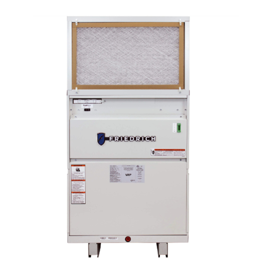
FreshAire™ System Set-Up and Operation FreshAire™ System Set-Up and Operation If equipped with the FreshAire™ System, the unit will come with a FreshAire filter and blank-off plate. Detail A Remove the blank-off plate prior to turning the unit on. If equipped with the FreshAire™ System, the unit will To remove the blank off plate, pull the attached tab come with a FreshAire Filter and Blank Off Plate. -
Page 28: Electrical Wiring Diagrams
Electrical Wiring Diagram - 208/230V... -
Page 29: Final Installation Checklist
The leaves the module through a filter and enters the operator of the equipment. Friedrich Warranty Service Company in the area optional system can be configured to have either a indoor space in front of the indoor conditioning coil. -
Page 30: Service And Warranty
Service & Warranty Servicing / Chassis Quick Change Outs To Remove the Chassis from the Closet: The chassis is designed for quick disconnect A. Switch the wall controller off. and change out. For minor electrical service, B. Disconnect the power coming into the unit from the Electrical Access Panel is easily removable the main breaker panel or the closet mounted once the screws are removed. -
Page 31: Accessories
Accessories ITEM DESCRIPTION CHECK LIST VRPXWPC-8 Wall Plenum for VRP12 with VRPXALA for 4” to 8” thick wall Require One of these Wall Plenums per unit VRPXWPC-14 Wall Plenum for VRP12 with VRPXALA for 8” to 14” thick wall VRPXALC Require One of these Architectural louver (VRP36 only) (30˚... - Page 32 Accessories TYPE ITEM DESCRIPTION CHECK LIST WALL VRPXWCT Wall Controller CONTROLLER Required one per unit VRPXWCT VRPXEMRT2 VRP Energy Management Wired Wall Controller with Occupancy Sensor Require One of the Controllers per unit VRPXEMWRT2 VRP Energy Management Wireless Wall Controller with Occupancy Sensor EMOCT Online Connection Kit –...
-
Page 33: Diagnostic Error Codes
Diagnostic Error Codes Code Description Return air thermistor open/shorted Indoor coil (cool inlet) thermistor open/shorted Outdoor coil (heat inlet) thermistor open/shorted Discharge air thermistor open/shorted Outdoor ambient thermistor open/shorted Indoor coil (heat cond.) thermistor open/shorted Compressor discharge thermistor open/shorted Compressor suction thermistor open/shorted Liquid cool thermistor open/shorted Liquid heat thermistor open/shorted Humidity sensor open/shorted... -
Page 34: Vrp Limited Warranty
FRIEDRICH will repair or replace, at its option, any defective part without charge for the part. Replacement parts are warranted for the remainder of the original warranty period. - Page 35 THIS PAGE INTENTIONALLY LEFT BLANK.
- Page 36 Variable Refrigerant Packaged Heat Pump Innovative | Intelligent | Inverter Friedrich Air Conditioning Co. | 10001 Reunion Place, Suite 500 | San Antonio, TX 78216 | 877.599.5665 | www.friedrich.com VRP36 IOM / 92303010_00...
Need help?
Do you have a question about the VRP36K and is the answer not in the manual?
Questions and answers