Table of Contents
Advertisement
Quick Links
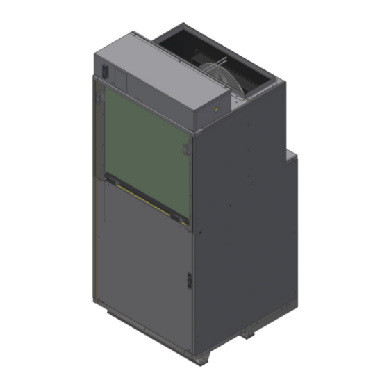
Single Package Vertical Heat Pump System
R-32 Refrigerant
9K
VHA - 09K25RCQ, 09K34RCQ, 09K50RCQ
VHA - 09R25RCQ, 09R34RCQ, 09R50RCQ
12K
VHA - 12K25RCQ, 12K34RCQ, 12K50RCQ
VHA - 12R25RCQ, 12R34RCQ, 12R50RCQ
18K
VHA - 18K25RCQ, 18K34RCQ, 18K50RCQ, 18K75RCQ
VHA - 18R25RCQ, 18R34RCQ, 18R50RCQ, 18R75RCQ
24K
VHA - 24K25RCQ, 24K34RCQ, 24K50RCQ, 24K75RCQ, 24K10RCQ
VHA - 24R25RCQ, 24R34RCQ, 24R50RCQ, 24R75RCQ, 24R10RCQ
95992014_00
THE EXPERTS IN ROOM AIR CONDITIONING
Advertisement
Table of Contents

Related Manuals for Friedrich VERT-I-PAK VHA-09K25RCQ


Summary of Contents for Friedrich VERT-I-PAK VHA-09K25RCQ
- Page 1 Single Package Vertical Heat Pump System R-32 Refrigerant VHA - 09K25RCQ, 09K34RCQ, 09K50RCQ VHA - 09R25RCQ, 09R34RCQ, 09R50RCQ VHA - 12K25RCQ, 12K34RCQ, 12K50RCQ VHA - 12R25RCQ, 12R34RCQ, 12R50RCQ VHA - 18K25RCQ, 18K34RCQ, 18K50RCQ, 18K75RCQ VHA - 18R25RCQ, 18R34RCQ, 18R50RCQ, 18R75RCQ VHA - 24K25RCQ, 24K34RCQ, 24K50RCQ, 24K75RCQ, 24K10RCQ VHA - 24R25RCQ, 24R34RCQ, 24R50RCQ, 24R75RCQ, 24R10RCQ 95992014_00...
-
Page 2: Table Of Contents
TABLE OF CONTENTS INTRODUCTION Important Safety Information Personal Injury Or Death Hazards Operation of Equipment in During Construction Equipment Identification Model Number Identification Guide Serial Number Identification Guide SPECIFICATIONS General Specifications Electrical Specifications Electrical Requirements Airflow Data (Condenser) Typical Installation Overview Chassis Dimensions 9K, 12K Chassis Dimensions, 18k Chassis Dimensions, 24k... - Page 3 TABLE OF CONTENTS 265V 3.4 kW 265V 5 kW 265V 7.5 kW 265V 7.5 kW APPENDIX Appendix 1 Thermistor Resistance Values (This Table Applies to All Thermistors) Required Accessories Interactive Parts Viewer Limited Warranty Friedrich Authorized Parts Depots...
-
Page 4: Introduction
INTRODUCTION Important Safety Information The information in this manual is intended for use by a qualified technician who is familiar with the safety procedures required for installation and repair, and who is equipped with the proper tools and test instruments required to service this product. Installation or repairs made by unqualified persons can result in subjecting the unqualified person making such repairs as well as the persons being served by the equipment to hazards resulting in injury or electrical shock which can be serious or even fatal. - Page 5 CAUTION: Do Not Operate Equipment During Active Stages Of Construction To ensure proper operation, Friedrich requires that all equipment is not operated during active construction phases. This includes active stages of completing framing, drywalling, spackling, sanding, painting, flooring, and moulding in the equipment’s designated conditioning space. The use of this equipment during construction could result in premature failure of the components and/or system and is in violation of our standard warranty guidelines.
-
Page 6: Personal Injury Or Death Hazards
INTRODUCTION Personal Injury Or Death Hazards WARNING AVERTISSEMENT ADVERTENCIA SAFETY Do not remove, disable or Ne pas supprime, désactiver No eliminar, desactivar o bypass this unit’s safety ou contourner cette l´unité pasar por alto los dispositi- FIRST devices. Doing so may des dispositifs de sécurité, vos de seguridad de la cause fire, injuries, or... - Page 7 INTRODUCTION Personal Injury Or Death Hazards • REFRIGERATION SYSTEM REPAIR HAZARDS: • Use approved standard refrigerant recovering procedures and equipment to relieve high pressure before opening system for repair. Reference EPA regulations (40 CFR Part 82, Subpart F ) Section 608. •...
-
Page 8: Operation Of Equipment In During Construction
INTRODUCTION Operation of Equipment in During Construction • OPERATION OF EQUIPMENT MUST BE AVOIDED DURING CONSTRUCTION PHASES WHICH WILL PRO- DUCE AIRBORNE DUST OR CONTAMINANTS NEAR OR AROUND AIR INTAKE OPENINGS: • Wood or metal framing; • Drywalling or sheathing, •... -
Page 9: Equipment Identification
INTRODUCTION This service manual is designed to be used in conjunction with the installation and operation manuals provided with each air conditioning system. This service manual was written to assist the professional service technician to quickly and accurately diagnose and repair malfunctions. Due to continuing research in new energy-saving technology, all information in this manual is subject to change without notice. -
Page 10: Model Number Identification Guide
INTRODUCTION Model Number Identification Guide MODEL NUMBER 09 K 34 RC Q Marketing Revision Series RT = R410a Refrigerant V = Vertical RC = R32 Refrigerant Electric Heater Size A Series HA = Air-Source Heat Pump 25 = 2.5 kW 34 = 3.4 kW Nominal Capacity 50 = 5.0 kW... -
Page 11: Specifications
SPECIFICATIONS General Specifications MODEL VHA09K VHA09R VHA12K VHA12R VHA18K VHA18R VHA24K VHA24R COOLING DATA TOTAL COOLING CAP. (Btu/hr) @95°F 9,400 9,400 11,200 11,200 17,800 17,800 22,600 22,600 SENSIBLE COOLING CAP. (Btu/hr) 7,100 7,100 8,800 8,800 13,100 13,100 14,700 14,700 SEER2 12.3 12.3 12.3... -
Page 12: Electrical Specifications
SPECIFICATIONS Electrical Specifications Total Total Electric Heat Electric Heat Electric Heat Compressor RLA Blower Motor Condenser Motor MOP/ Vert-I-Pak Family Model Number Refrigeration Amps Amps Watts Amps FLA/HP FLA/HP MOCP 25RCQ 5.6/5.3 11.5/10.4 2450/2000 10.7/9.6 14.4 4.1/3.8 VHA09K 34RCQ 5.6/5.3 15.4/14.0 3350/2740 14.6/13.2... - Page 13 SPECIFICATIONS Indoor CFM & External Static Pressure Vert-I-Pak is designed to install through an exterior wall with a plenum (VPAWP1-8, VPAWP1-14) and an external louver. If the default plenum and louver combinations are not used, the selections and design must be evaluated by us to ensure the total pressure drop does not exceed the maximum allowable limits.
-
Page 14: Airflow Data (Condenser)
VHA24 0.03 0.12 If the Friedrich designed plenum and louver combinations are not used, the selections and design must be evaluated by Friedrich to ensure the total pressure drop does not exceed the maximum allowable limits. Typical Installation Overview VPDP2 drain pan required... -
Page 15: Chassis Dimensions 9K, 12K
SPECIFICATIONS Chassis Dimensions 9K, 12K Side Front Side 23 1/4" SUPPLY 23 1/8" 8 21/64" 4 59/64" 3 11/16" 9 7/16" 2 13/32" CONDENSER INLET AIR ELECTRICAL ENTRY RETURN 29 1/2" CONDENSER EXHAUST 16 7/64" 14 11/64" 2 21/32" 2 21/32" 1 1/2"... -
Page 16: Chassis Dimensions, 18K
DATE DATE ARE IN INCHES "THE DESIGN AND DETAIL OF THIS DRAWING IS CONFIDENTIAL AND PROPRIETARY TO FRIEDRICH AIR CONDITIONING CO. DO NOT SCALE DRAWINGS AND SHALL NOT BE DISCLOSED TO ANYONE WITHOUT PRIOR WRITTEN AUTHORIZATION OF FRIEDRICH." WORK TO DIMENSIONS 19.178... -
Page 17: Chassis Dimensions, 24K
ARE IN INCHES H PRODUCT ENGINEERING MUST BE NOTIFIED PRIOR TO ANY DESIRED SPECIFICATION CHANGES. "THE DESIGN AND DETAIL OF THIS DRAWING IS CONFIDENTIAL AND PROPRIETARY TO FRIEDRICH AIR CONDITIONING CO. DO NOT SCALE DRAWINGS AND SHALL NOT BE DISCLOSED TO ANYONE WITHOUT PRIOR WRITTEN AUTHORIZATION OF FRIEDRICH."... -
Page 18: Required Minimum Clearances
72” UNIT must be kept. FENCE MAJOR OBSTRUCTIONS The the example pictured above is for reference only and does not represent all possible installations. Please contact Friedrich Air Conditioning for information regarding effects of other installation arrangements. Figure 205... - Page 19 SPECIFICATIONS Closet Orientations & Dimensions 23 1/8" 26 1/8" 3" 23 1/8" 27" 29 1/8" 4 1/2 ...
- Page 20 SPECIFICATIONS Closet View Rigid Ductwork Field-supplied Filter (25" x 20") Exterior Wall 58" Flexible Ductwork Transition Duct Power VPAWP1-8/1-14 Wall Plenum Disconnect Plenum Divider 29" VPRG4/VPRG4R Access Panel & Return Air Filter Grille Optional Platform Optimal Clearance on VPDP2 drain pan beneath either sides minimum for unit is required on all 18K Chassis is shipped...
- Page 21 SPECIFICATIONS Wall Opening Dimensions Wall Opening Dimensions Exterior Wall Plenum Cut-Out Dimensions (W x H): 24 5/8” x 30 7/8” 1” NOTE: The distance between the rough opening and the finished floor/platform must be 1 1 ” ” . . Return Air Access Door Wall Cut-Out 27”...
-
Page 22: Operation
OPERATION Sequence of Operation Power-up When power is applied to the unit (230 VAC), L1 and L2 provide power to energize all relays, contactors, and control boards receive power. 1 leg of the compressor is energized. Power is supplied to the transformer which provides 24 VAC to the thermostat and the defrost control board. - Page 23 OPERATION Sequence of Operation Compressor Delay Time At the beginning of the defrost cycle the compressor is shut off for 30 seconds and then the reversing valve is de-energized. At the end of the defrost cycle, the compressor will be shut off for 30 seconds before the reversing valve is energized. Following a 30 second delay, the compressor will be turned back on.
- Page 24 OPERATION Sequence of Operation Defrost Mode Operation When the unit goes into heat pump mode for the first time and the outdoor coil temp drops below 30 ˚F it will run a defrost to calibrate the control even though there is no ice build up. Normally the unit will go into defrost when the outdoor coil temp sensor provides signal to the board reads below 30 ˚F and the defrost control board detects a frost condition based on the the calibration point and the ambient temp sensor.
- Page 25 OPERATION Sequence of Operation Defrost Mode Termination Once a defrost mode has been initiated, it shall be terminated immediately and reset the internal timing if the coil sensor temperature exceeds the selected termination temperature. If the temperature select shunt is not installed, the default termination temperature shall be 50°F.
-
Page 26: Defrost Control Board
OPERATION Defrost Control Board Inputs C - 24 VAC Common R - 24 VAC Output (Power Supply) supplied via the transformer to the thermostat. Y - 24 VAC thermostat input for compressor demand - Thermostat Call for Compressor (“Y”). This signal is monitored by the control logic, and is recognized as active when “R”... -
Page 27: Remote Thermostat Connection
OPERATION Remote Thermostat Connection Remote Wall Thermostat Location The thermostat should not be mounted where it may be affected by drafts, discharge air from registers (hot or cold), or heat radiated from the sun appliances, windows etc.. The thermostat should be located about 3-5 Ft. above the floor in an area of average temperature, with good air circulation. -
Page 28: General Knowledge Sequence Of Refrigeration
OPERATION General Knowledge Sequence Of Refrigeration A good understanding of the basic operation of the refrigeration system is essential for the service technician. Without this understanding, accurate troubleshooting of refrigeration system problems will be more difficult and time consuming, if not (in some cases) entirely impossible. The refrigeration system uses four basic principles in its operation which are as follows: “Heat always flows from a warmer body to a cooler body.”... -
Page 29: Remove And Install The Chassis
REMOVE AND INSTALL THE CHASSIS WARNING WARNING ELECTRIC SHOCK HAZARD Turn off electric power before service or installation. CUT/SEVER HAZARD All electrical connections and wiring MUST be Be careful with the sharp edges and corners. Wear protective clothing and gloves, etc. the National Electrical Code and all local codes which have jurisdiction. -
Page 30: External Static Pressure
EXTERNAL STATIC PRESSURE External Static Pressure can best be described as the pressure difference (drop) between the Positive Pressure (discharge) and the Negative Pressure (intake) sides of the blower. External Static Pressure is developed by the blower as a result of resistance to airflow (Friction) in the air distribution system EXTERNAL to the VERT-I-PAK cabinet. -
Page 31: Explanation Of Tables
External Static Pressure Correct CFM (if needed): Correction Multipliers 230V 1.00 208V 0.97 265V Heating 1.00 Cooling 0.95 Table 602 (Correction Multiplier) Explanation of Tables Table 601 is the nominal dry coil VERT-I-PAK CFMs. Table 602 is the correction factors beyond nominal conditions. 1 ½... -
Page 32: Fresh Air Door
External Static Pressure Fresh Air Door The Fresh Air Door is an “intake” system. The fresh air door opened via a slide on the front of the chassis located just above the indoor coil. Move the slide left to open and right to close the fresh air door. The system is capable of up to 60 CFM of fresh air @ ~.3” H2O internal static pressure. -
Page 33: Troubleshooting
TROUBLESHOOTING Control Diagnostic Modes Control Diagnostic Modes Diagnostic Description LED 1 LED 2 Solution Control Fault (No Power) Confirm incoming voltage, if present replace the board. Normal Operation Flash Flash Normal operation. Anti-Short Cycle Delay Alternating Wait for shot cycle delay to expire. Approximately 3-minutes. Flash Coil Sensor Failure 1. -
Page 34: Component Identification
COMPONENT IDENTIFICATION Electrical Control Box 9K & 12k CONTACTOR SAFETY RELAY DEFROST HEAT RELAY HEAT RELAY AIRFLOW SWITCH 230V TRANSFORMER CAPACITOR TERMINAL STRIP BASEPAN HEAT FUSES 24V TRANSFORMER DEFROST RELAY DEFROST CONTROL BOARD INDOOR BLOWER CONTROL BOARD INDOOR FAN SPEED RELAY 265V 30a TRANSFORMER FUSES TERMINAL BLOCK ELECTRICAL DISCONNECT... - Page 35 COMPONENT IDENTIFICATION Electrical Control Box 9K & 12k...
-
Page 36: Electrical Control Box 18K & 24K
COMPONENT IDENTIFICATION Electrical Control Box 18K & 24k 230V TRANSFORMER HEAT RELAY DEFROST HEAT RELAY SAFETY RELAY BASEPAN FUSES CAPACITOR CONTACTOR DEFROST RELAY TERMINALS 24V TRANSFORMER INDOOR BLOWER CONTROLLER AIRFLOW SWITCH ELECTRICAL DISCONNECT 230V TRANSFORMER FUSES INDOOR FAN RELAY 24V TRANSFORMER FUSE DEFROST CONTROLLER TERMINALS Figure 603 (18 &... -
Page 37: Defrost Control Board
COMPONENT IDENTIFICATION Defrost Control Board FAULT CODE DESCRIPTIONS CONDENSER FAN OUT COMPRESSOR OUT TEST TERMINALS (FORCE DEFROST) DEFROST CONTROL HIGH PRESSURE TEMPERATURE SWITCH SELECTION SHUNT FAULT CODE LED 2 FAULT CODE LED 1 THERMOSTSAT INPUTS LOW PRESSURE SWITCH REVERSING VALVE B- OUT C- COMMON P4 CONDENSER COIL SENSOR... -
Page 38: Component Testing
COMPONENT TESTING Reversing Valve A reversing valve is a component of a heat pump that changes the direction of WARNING refrigerant flow, allowing the system to function in both heating and cooling modes. ELECTRIC SHOCK HAZARD It consists of a pressure-operated, main valve and a pilot valve actuated by Disconnect power to the unit before a solenoid plunger. -
Page 39: Compressor Checks
COMPONENT TESTING Compressor Checks WARNING WARNING ELECTRIC SHOCK HAZARD BURN HAZARD Turn off electric power before service or installation. Proper safety procedures must be followed, All electrical connections and wiring MUST be and proper protective clothing must be worn when working with a torch. the National Electrical Code and all local codes which have jurisdiction. -
Page 40: Ground Test
COMPONENT TESTING Compressor Checks WARNING WARNING HIGH PRESSURE HAZARD ELECTRIC SHOCK HAZARD Sealed Refrigeration System contains refrigerant Turn off electric power before service or and oil under high pressure. installation. Extreme care must be used, if it becomes necessary to work on equipment with Proper safety procedures must be followed, and proper protective clothing must be worn power applied. -
Page 41: Components Testing
COMPONENTS TESTING Heating Element and Limit Switches All models are equipped with a dual heating element. Each element has a WARNING primary limit switch (bimetal thermostat). Should the blower motor fail, filter become clogged or air-flow be restricted etc., the high limit switch will open SYMBOL REVISIONS E.C.R... -
Page 42: Heater Assembly Removal 9 And 12K
COMPONENTS TESTING Heater Assembly Removal 9 and 12k 1. Remove electrical box cover. 2. Disconnect Wiring. 4. Remove 2 screws. 5. Carefully unhook heater assembly from rear hook and slide out of the unit. Remove Screws 2 places Figure 610 Hook Figure 611... -
Page 43: Heater Assembly Removal 18K And 24K
COMPONENTS TESTING Heater Assembly Removal 18k and 24k 1. Remove right side access panel. 2. Disconnect Wiring. 3. Remove 2 screws. 4. Carefully unhook heater assembly from rear hook and slide out of the unit. Heater Access Panel Figure 6 Figure 612 Figure 613... -
Page 44: Drain Pan Valve
COMPONENTS TESTING Drain Pan Valve WARNING Bellows Assembly Drain Pan Valve ELECTRIC SHOCK HAZARD Turn off electric power before service or installation. Extreme care must be used, if it becomes necessary to work on equipment with power applied. Failure to do so could result in serious injury or death. -
Page 45: Check Evaporator Blower Motor And Control Board
COMPONENT TESTING Check Evaporator Blower Motor and Control Board Check for 230 VAC at Repair Wiring L1 to L2 Trace Wiring or replace (5 Pin Connector on ID back to contactor as Control Board) Contactor required Check for 230 VAC at Trace Wiring Repair Wiring L2 to... -
Page 46: Replace Evaporator Blower Motor (18 & 24K)
COMPONENT TESTING Replace Evaporator Blower Motor (18 & 24k) 1. Unit needs to be removed from sleeve or closet to facilitate fan 6. Remove 3 screws on right side. replacement. Refer to Chassis Removal 2. Remove electrical box cover. 3. Disconnect the terminals and the P3 cable connector on the indoor fan motor controller. -
Page 47: Outdoor Fan Check
COMPONENT TESTING Outdoor Fan Check 1. Remove Electrical box cover. 2. Ensure that unit is running with a demand for outdoor fan. 3. Check for 230/ 265 VAC by placing multimeter probes on Con- tactor Terminal and fan Out terminal of the defrost control board. 4. -
Page 48: Outdoor Fan Replacement 9 & 12K
COMPONENT TESTING Outdoor Fan Replacement 9 & 12k 1. Remove chassis from closet. Refer to chassis removal. 7. Remove 2 screws on each side of shroud. 2. Remove electrical box cover. 3. Remove left and right side access panels. NOTE: For blade replacement only, disconnection of fan motor wires is not required Remove 2 screws on each side of shroud Disconnect... -
Page 49: Outdoor Fan Replacement 18 & 24K
COMPONENT TESTING Outdoor Fan Replacement 18 & 24k 1. Remove chassis from closet. Refer to chassis removal. 6. Pull some slack out of white wire in the bundle to facilitate fan 2. Remove left and right side lower access panels. removal.. - Page 50 COMPONENT TESTING Outdoor Fan Replacement 18&24k 8. Remove 2 screws on rear panel. 10. Loosen set screw to remove fan blade. Remove 2 screws from rear Loosen Set Screw 9. Remove four fan mounting screws and ground wire. 11. Remove 3 screws from fan motor bracket. Remove mounting bolts (4 places) Remove Motor...
-
Page 51: Basepan Heater
COMPONENT TESTING Basepan Heater To check the basepan heater operation; 1. Access the electrical box 2. With Power removed from the unit ohm out the 1 amp in line fuses located behind the electrical box. a. If fuse is open - check the heater element wiring by ohming out the wiring to each side and to ground. b. -
Page 52: R-32 Sealed System Repair
R-32 SEALED SYSTEM REPAIR General Information WARNING: Electrical Shock Hazard Disconnect all power to the unit before starting maintenance. All electrical connections and wiring MUST be installed by a qualified electrician and conform to all codes which have jurisdiction. Failure to do so can result in property damage, severe electrical shock or death. - Page 53 R-32 SEALED SYSTEM REPAIR General Information Warning: No ignition sources: No person carrying out work in relation to a REFRIGERATING SYSTEM which involves exposing any pipe work shall use any sources of ignition in such a manner that it may lead to the risk of fire or explosion. All possible ignition sources, including cigarette smoking, should be kept sufficiently far away from the site of installation, repairing, removing and disposal, during which refrigerant can possibly be released to the surrounding space.
-
Page 54: Required Equipment
R-32 SEALED SYSTEM REPAIR Required Equipment • Nitrogen regulator for purging and testing, rated to 800 psi. (Capable of low psi flow) • Pipe tubing cutter. • Refrigerant recovery cylinder. (Flammable A2L label) • Ventilation fan. • Class ABC fire extinguisher. •... -
Page 55: Refrigerant Removal, Recovery, And Evacuation
R-32 SEALED SYSTEM REPAIR Refrigerant Removal, Recovery, and Evacuation NOTE: When accessing the refrigerant in the system to make repairs or for any other purpose, conventional procedures shall be used. However, for FLAMMABLE REFRIGERANTS (R-32 is classified in the A2L group for mildly flammable refrigerants) it is important that best practice is followed since flammability is a consideration. -
Page 56: Component Replacement/Brazing
R-32 SEALED SYSTEM REPAIR Component Replacement/Brazing Warning: • Ensure sufficient ventilation at the repair place. Warning: Presence of fire extinguisher. If any hot work is to be conducted on the refrigerating equipment or any associated parts, have a ABC class fire extinguisher available to hand. Warning: No person carrying out work in relation to a REFRIGERATING SYSTEM which involves exposing any pipe work shall use any sources of ignition in such a manner that it may lead to the risk of fire or explosion. -
Page 57: Refrigerant Charging
R-32 SEALED SYSTEM REPAIRS Refrigerant Charging WARNING: Electrical Shock Hazard Disconnect all power to the unit before starting maintenance. All electrical connections and wiring MUST be installed by a qualified electrician and conform to all codes which have jurisdiction. Failure to do so can result in property damage, severe electrical shock or death. WARNING: This Product uses R-32 Refrigerant Do not use means to accelerate the defrosting process or to clean, other than those recommended by the manufacturer. -
Page 58: Compressor Replacement
R-32 SEALED SYSTEM REPAIRS Compressor Replacement 1. Be certain to perform all necessary electrical and refrigeration tests to be sure the compressor is actually defective before replacing. 2. Recover all refrigerant from the system though the process tubes. Refer to Refrigerant Removal, Recovery, and Evacuation Section of this WARNING... -
Page 59: Compressor Replacement -Special Procedure In Case Of Compressor Burnout
R-32 SEALED SYSTEM REPAIRS Compressor Replacement -Special Procedure in Case of Compressor Burnout 1. Recover all refrigerant and oil from the system. Refer to Refrigerant Removal, Recovery, and Evacuation Section of this manual. 2. Cut and remove compressor and capillary tube from the system. CAUTION: Seal all openings on the defective compressor immediately. -
Page 60: Replace The Reversing Valve
R-32 SEALED SYSTEM REPAIR Replace The Reversing Valve WARNING WARNING HIGH PRESSURE HAZARD EXPLOSION HAZARD Sealed Refrigeration System contains refrigerant The use of nitrogen requires a pressure and oil under high pressure. regulator. Follow all safety procedures and wear protective safety clothing etc. Proper safety procedures must be followed, and PPE must be utilized Failure to follow proper safety procedures... - Page 61 R-32 REFRIGERANT SYSTEM REPAIR TXV Replacement Please follow the steps below when replacing TXV: 1. Disassemble the front panel. WARNING 2. Remove the thermal bulb down by undoing the insulation around it. HIGH PRESSURE HAZARD 3. Recover all refrigerant from the system though the process tubes. Sealed Refrigeration System contains refrigerant and oil under high pressure.
-
Page 62: Wiring Diagrams
WIRING DIAGRAMS Figure 801 208/230V 2.5 kW 22100541_00 LABEL WIRING DIAG VPAK 2.5kW 230V BASEPAN HEATER(S) COMPRESSOR OD MOTOR ELECTRIC HEATER PRESSURE 2 A FUSE SWITCH XFMR CONTACTOR CAPACITOR KEY: DR- DEFROST RELAY HR-HEAT RELAY IMR-INDOOR MOTOR RELAY SR-SAFETY RELAY DHR- DEFROST HEAT RELAY CRDB... -
Page 63: 208/230V 3.4 Kw
WIRING DIAGRAMS Figure 802 208/230V 3.4 kW 22100542_00 LABEL WIRING DIAG VPAK 3.4kW 230V BASEPAN HEATER(S) COMPRESSOR OD MOTOR ELECTRIC HEATER PRESSURE 2 A FUSE SWITCH XFMR CONTACTOR CAPACITOR KEY: DR- DEFROST RELAY HR-HEAT RELAY IMR-INDOOR MOTOR RELAY SR-SAFETY RELAY DHR- DEFROST HEAT RELAY CRDB... -
Page 64: 208/230V 5.0 Kw
WIRING DIAGRAMS Figure 803 208/230V 5.0 kW 22100543_00 LABEL WIRING DIAG VPAK 5.0kW 230V BASEPAN HEATER(S) COMPRESSOR OD MOTOR ELECTRIC HEATER PRESSURE 2 A FUSE SWITCH XFMR CONTACTOR CAPACITOR KEY: DR- DEFROST RELAY HR-HEAT RELAY IMR-INDOOR MOTOR RELAY SR-SAFETY RELAY DHR- DEFROST HEAT RELAY CR DB... -
Page 65: 208/230V 7.5 Kw
WIRING DIAGRAMS Figure 804 208/230V 7.5 kW 22100544_00 LABEL WIRING DIAG VPAK 7.5kW 230V BASEPAN HEATER(S) COMPRESSOR OD MOTOR ELECTRIC HEATER PRESSURE 2 A FUSE SWITCH XFMR CONTACTOR CAPACITOR KEY: DR- DEFROST RELAY HR-HEAT RELAY IMR-INDOOR MOTOR RELAY SR-SAFETY RELAY DHR- DEFROST HEAT RELAY CR DB... -
Page 66: 208/230V 10 Kw
WIRING DIAGRAMS Figure 805 208/230V 10 kW 22100547_00 LABEL WIRING DIAG VPAK 10.0kW 230V BASEPAN HEATER(S) COMPRESSOR OD MOTOR ELECTRIC HEATER PRESSURE 2 A FUSE SWITCH XFMR CONTACTOR CAPACITOR KEY: DR- DEFROST RELAY HR-HEAT RELAY IMR-INDOOR MOTOR RELAY SR-SAFETY RELAY DHR- DEFROST HEAT RELAY CR DB... -
Page 67: 265V 2.5 Kw
WIRING DIAGRAMS Figure 806 265V 2.5 kW 22100548_00 LABEL WIRING DIAG VPAK 2.5kW 265V BASEPAN HEATER(S) COMPRESSOR OD MOTOR ELECTRIC HEATER PRESSURE 2 A FUSE SWITCH XFMR CONTACTOR CAPACITOR KEY: DR- DEFROST RELAY HR-HEAT RELAY IMR-INDOOR MOTOR RELAY SR-SAFETY RELAY DHR- DEFROST HEAT RELAY CR DB... -
Page 68: 265V 3.4 Kw
WIRING DIAGRAMS Figure 807 265V 3.4 kW 22100549_00 LABEL WIRING DIAG VPAK 3.4kW 265V BASEPAN HEATER(S) COMPRESSOR OD MOTOR ELECTRIC HEATER PRESSURE 2 A FUSE SWITCH XFMR CONTACTOR CAPACITOR KEY: DR- DEFROST RELAY HR-HEAT RELAY IMR-INDOOR MOTOR RELAY SR-SAFETY RELAY DHR- DEFROST HEAT RELAY CR DB... -
Page 69: 265V 5 Kw
WIRING DIAGRAMS Figure 808 265V 5 kW 22100550_00 LABEL WIRING DIAG VPAK 5.0kW 265V BASEPAN HEATER(S) COMPRESSOR OD MOTOR ELECTRIC HEATER PRESSURE 2 A FUSE SWITCH XFMR CONTACTOR CAPACITOR KEY: DR- DEFROST RELAY HR-HEAT RELAY IMR-INDOOR MOTOR RELAY SR-SAFETY RELAY DHR- DEFROST HEAT RELAY CR DB... -
Page 70: 265V 7.5 Kw
WIRING DIAGRAMS Figure 809 265V 7.5 kW 22100551_00 LABEL WIRING DIAG VPAK 7.5kW 265V BASEPAN HEATER(S) COMPRESSOR OD MOTOR ELECTRIC HEATER PRESSURE 2 A FUSE SWITCH XFMR CONTACTOR CAPACITOR KEY: DR- DEFROST RELAY HR-HEAT RELAY IMR-INDOOR MOTOR RELAY SR-SAFETY RELAY DHR- DEFROST HEAT RELAY CRDB... -
Page 71: 265V 7.5 Kw
WIRING DIAGRAMS Figure 810 265V 7.5 kW 22100552_00 LABEL WIRING DIAG VPAK 10.0kW 265V BASEPAN HEATER(S) COMPRESSOR OD MOTOR ELECTRIC HEATER PRESSURE 2 A FUSE SWITCH XFMR CONTACTOR CAPACITOR KEY: DR- DEFROST RELAY HR-HEAT RELAY IMR-INDOOR MOTOR RELAY SR-SAFETY RELAY DHR- DEFROST HEAT RELAY CRDB... -
Page 72: Appendix
APPENDIX Appendix 1 Thermistor Resistance Values (This Table Applies to All Thermistors) RESISTANCE TEMP RESISTENCE (K Ohms) TOLERANCE % CENTR 210.889 225.548 240.224 6.50 6.51 178.952 190.889 202.825 6.25 6.25 151.591 161.325 171.059 6.03 6.03 128.434 136.363 144.292 5.81 5.81 108.886 115.340 121.794... -
Page 73: Required Accessories
APPENDIX Required Accessories REQUIRED ACCESSORIES ARCHITECTURAL LOUVER VPAL2 and VPAL2-42 Extruded aluminum grille (30° or 42° blade angle) that attaches to the outdoor section of the wall plenum. VPDP2 VPSC2 and VPSC2-42 VPAL2 and VPAL2-42 in custom colors. DIMENSIONS: 25 9/16" W x 31 1/16" H WALL PLENUM VPAWP1-8, VPAWP1-14 VPAL2... -
Page 74: Interactive Parts Viewer
APPENDIX Interactive Parts Viewer All Friedrich Service Parts can be found on our online interactive parts viewer. Please click on the link below: Interactive Parts Viewer For Further Assistance contact Friedrich customer service at (1-800-541-6645). Limited Warranty Current warranty information can be obtained by referring to... -
Page 75: Friedrich Authorized Parts Depots
APPENDIX Friedrich Authorized Parts Depots NEUCO Inc. Reeve Air Conditioning, Inc. The Gabbert Company 2501 South Park Road 515 W Crossroads Parkway 6868 Ardmore Hallandale, Florida 33009 Bolingbrook, IL 60440 Houston, Texas 77054 312.809.1418 954-962-0252 borr@neuco.com 713-747-4110 800-962-3383 800-458-4110 United Products Distributors Inc.
Need help?
Do you have a question about the VERT-I-PAK VHA-09K25RCQ and is the answer not in the manual?
Questions and answers
I am the user of a unit VHA12K50RCO. Heat exchange unit. I am unfamiliar with this kind of unit and am seeking information on user function. I find there are very prolonged run times and to reduce temperature from 83 78 deg or 82 to 78 deg of cooling takes up to 5hr. I live on the south facing hot side of a building. When 78 degree temp is reached the unit does not shut of or cycle down and continues to run. I am used to the cease operation of an air conditioner so ask is this a normal function? Not turning off?.