Table of Contents
Advertisement
Advertisement
Table of Contents
Troubleshooting

Related Manuals for Friedrich VRP7k


Summary of Contents for Friedrich VRP7k
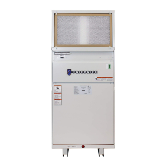
- Page 1 Model Voltage VRP7k 7,000 VRP7r 7,000 95261402_00...
-
Page 2: Table Of Contents
TABLE OF CONTENTS INTRODUCTION‑ Important Safety Information‑ Personal Injury Or Death Hazards‑ Model and Serial Identification Guide‑ INTRODUCTION‑ VRP® Variable Speed System vs. Fixed‑speed System‑ FreshAire™ Conditioned Fresh Air‑ Reheat Coil ‑ Augments VRP’s Dehumidification Capability‑ Basepan Heater‑ SPECIFICATIONS‑ Cooling Performance‑ 7k Performance Curves‑... - Page 3 Diagnostic Code (Temperature Based)‑ WIRING DIAGRAMS‑ 208/230V 2.5 & 3.4 kW‑ 265V 2.5 & 3.4 kW‑ PARTS CATALOG‑ Main Diagram‑ Control Box Diagram‑ Control Box Wiring‑ ACCESSORIES‑ Accessories ‑ Drain Kit‑ CUSTOMER SATISFACTION and QUALITY ASSURANCE‑ FRIEDRICH AUTHORIZED PARTS DEPOTS‑...
-
Page 4: Introduction
INTRODUCTION Important Safety Information The information in this manual is intended for use by a qualified technician who is familiar with the safety proce- dures required for installation and repair, and who is equipped with the proper tools and test instruments required to service this product. -
Page 5: Personal Injury Or Death Hazards
INTRODUCTION Personal Injury Or Death Hazards WARNING AVERTISSEMENT ADVERTENCIA SAFETY Do not remove, disable or Ne pas supprime, désactiver No eliminar, desactivar o bypass this unit’s safety ou contourner cette l´unité pasar por alto los dispositi- FIRST devices. Doing so may des dispositifs de sécurité, vos de seguridad de la cause fire, Doing so may... - Page 6 INTRODUCTION Personal Injury Or Death Hazards • REFRIGERATION SYSTEM REPAIR HAZARDS: • Use approved standard refrigerant recovering procedures and equipment to relieve high pressure before open- ing system for repair. • Do not allow liquid refrigerant to contact skin. Direct contact with liquid refrigerant can result in minor to moder- ate injury.
-
Page 7: Model And Serial Identification Guide
INTRODUCTION Model and Serial Identification Guide Series Engineering code S = No Extra Options VRP Heat Pump L = Basepan Heat Nominal Capacity (Btu /Hr.) 07 = 3,300 - 9,000 Operating range Plenum and louver con guration D= Only for 7000 Btu units Voltage K = 230/208 V R = 265 V... -
Page 8: Introduction
In sum, The Friedrich VRP offers a significant value to all parties involved in the design and construction of a new building. Because of the simpler and more straightforward nature of the packaged design, and the ability to potentially downsize or eliminate additional make up air and humidity control equipment, the VRP reduces much of the headache and complexity facing the design engineer. -
Page 9: Vrp® Variable Speed System Vs. Fixed-Speed System
INTRODUCTION VRP® Variable Speed System vs. Fixed-speed System Low Ambient Heat Pump Performance: Variable speed technology enables VRP units to supply continuous hot air in heat pump mode even at low outdoor ambient temperatures. This reduces strip heat usage resulting in exceptional savings with VRP units when compared with Precise Temperature &... -
Page 10: Freshaire™ Conditioned Fresh Air
INTRODUCTION FreshAire™ Conditioned Fresh Air FreshAire, is a dedicated fresh air system that brings in up t o 35 CFM of outdoor air int o the VRP® unit. The FreshAire system uses one fan to bring in fresh outside air into the the unit. The outdoor air passes through dedicated 6”x 6”x1” MERV 8 filter that are easily replaceable from the front of the unit. -
Page 11: Reheat Coil - Augments Vrp's Dehumidification Capability
INTRODUCTION Reheat Coil - Augments VRP’s Dehumidification Capability Temperature differences are not the only source of discomfort in a living space. Humidity also plays a big role — especially in climates that tend to be both hot and humid. The air conditioning industry’s focus on humidity issues has elevated the importance of dehumidification. -
Page 12: Basepan Heater
INTRODUCTION Basepan Heater Basepan Heater Basepan Heat Thermostat VRP model numbers that end with the ‘L’ character will come equipped with a basepan heater. The outdoor tem perature at which the basepan heat engages can be set via an analog thermostat. The “MIN” setting will turn on the basepan heat at 0ºF outdoor ambient. -
Page 13: Specifications
SPECIFICATIONS Cooling Performance Model VRP7K / VRP7R Cooling Performance Data (Cooling Standards: 95°F DB/75°F WB outdoor, 80°F DB/67°F WB indoor) Voltage 230/208 Cooling Btu (Rated) 7,000 Cooling Btu (Min. – Max) 3,300‑9,000 Outdoor Operating Range (°F) 55 – 115 Power (W) SEER 15.5... -
Page 14: 7K Performance Curves
SPECIFICATIONS 7k Performance Curves Rounded Extended Performance Chart 70 °F WB 75 °F WB 80 °F WB 85 °F WB 90 °F WB 60 °F WB 63 °F WB 67 °F WB 71 °F WB 73 °F WB (°F) 65 7790 450 2.3 8505 450 2.3 9220 450 2.3 9935 450 2.3 10655 455 2.3 70 7480 475 2.4 8170 475 2.4 8850 480 2.4 9530 480 2.4 10220 480 2.4 75 7175 505 2.6 7830 505 2.6 8480 510 2.6 9130 510 2.6 9785 510 2.6... -
Page 15: Air Flow Data -7K
ESP (“WC) 0.02 0.08 NOTE: If the Friedrich designed plenum and louver combinations are not used, the louver/duct design must be evaluated by the factory to insure the total pressure drop does not exceed the maximum allow able limits. Figure 204... -
Page 16: Electrical Data
SPECIFICATIONS Electrical Data Electrical Data Total Electric Electric Electric Heater Heating ID Blower OD Blower Heating MOP / MOCP VRP Model Voltage Watts Amps Amps Amps 2500 8530 11.5 VRP07K 14.4 2045 6980 10.6 5000 11600 15.4 19.3 4100 9490 14.1 VRP07R 2500... -
Page 17: 7K Unit Installation Dimensional Data
SPECIFICATIONS 7k Unit Installation Dimensional Data 20 7/8" 23" 1" 4 5/8" 21 1/4" 9 11/16" 43" ELECTRICAL ENTRY (EACH SIDE) 31" 17 1/4" 20 3/4" 2 1/2" 20 3/4" Model VRP07K VRP07R Dimensions (W x D x H) 23" x 23" x 45 3/8" Net Weight (lbs.) Shipping Weight (lbs.) R410A Charge (oz.) -
Page 18: 7K Installation Types
SPECIFICATIONS Installation Types 7k Installation Types 23 1/8" 26 1/8" 3" 23 1/8" 27" 29 1/8" 3 ... -
Page 19: 7K Wall Opening Dimensiions
SPECIFICATIONS Wall Opening Dimensions 7k Wall Opening Dimensiions Exterior Rough Opening EXTERIOR WALL OPENING DIMENSIONS Unit 24 5/8" 30 7/8" NOTE: The distance between the rough opening and the finished floor/platform must be 3/4" 3/4” Interior (Access Door) Rough Opening INTERIOR WALL OPENING DIMENSIONS Unit 27"... -
Page 20: Accessories Dimensional Data-Louvers & Wall-Plenums
Accessories Dimensional Data-Louvers & Wall-Plenums SPECIFICATIONS 7k Accessories Dimensional Data-Louvers & Wall-Plenums Architectural Louver ” VPAL2/VPSC2 ” " " Wall Plenum VPAWP1-8 - telescopes from 5- ” to 8” VPAWP1-14 - telescopes from 8” to 14” Figure 209... -
Page 21: Operation
OPERATION Sequence Of Operations Cooling Sequence: The wall thermostat provides the temperature set point as well as the current dry bulb temperature and relative humidity. Upon a call for cooling, the compressor modulates based on the difference between room temperature and set point. As cooling demand decreases the compressor will modulate to a minimum speed. -
Page 22: Wall Controller Operation
OPERATION Wall Controller Operation Wall Controller Operation VRPXWC Control Only Locked Wait Cool Heat Mode: Temperature Cycles between Increment ‘Up’ Heat, Cool or Fan Only Fan: AUTO FAN Sets fan to either Temperature CONTINUOUS -cycle automatically Increment ‘Down’ run continuously Speed: SET POINT ON/OFF... - Page 23 OPERATION Wall Controller Control Only Locked Wait Cool Heat Mode: Cycles between Temperature Heat, Cool or Fan Only Increment ‘Up’ Fan: AUTO FAN Temperature Sets fan to either CONTINUOUS Increment ‘Down’ cycle automatically or run continuously SET POINT ON/OFF: ROOM TEMP Speed: Turn unit CHECK...
-
Page 24: Freshaire Control
OPERATION FreshAire Control • To engage the FreshAire system, flip the switch into the ‘ON’ position. -
Page 25: Vrp Required Minimum Clearances
UNIT of 72” must be kept. FENCE MAJOR OBSTRUCTIONS The the example pictured above is for reference only and does not represent all possible installations. Please contact Friedrich Air Conditioning for information regarding effects of other installation arrangements. -
Page 26: Installation Orientation
INSTALLATION Installation Orientations Installation Orientation 23 1/8" 26 1/8" 3" 23 1/8" 27" 29 1/8" 3 23 1/8"... -
Page 27: Exterior Wall Opening Dimensions
INSTALLATION Exterior Wall Opening Dimensions Exterior Wall Opening Dimensions Exterior Wall Rough Opening Dimensions Unit Width Heigth VPAWP1-* 24 5/8" 30 7/8" NOTE: The distance between the rough opening and the finished floor/platform must be 3/4”. 3/4”... -
Page 28: Interior(Closet) Wall Opening Dimensions
INSTALLATION Interior (Closet) Wall Opening Dimensions Interior(Closet) Wall Opening Dimensions Return Air Access Door Wall Cut-Out 27” 55 3/4” NOTE: To maintain ease of removal and serviceability, if the unit is installed on a platform ensure that the total height of the unit from the floor does not exceed the height of the interior rough opening. -
Page 29: Preliminary Plumbing
INSTALLATION Preliminary Plumbing Preliminary Plumbing Standard (Front Install) The image to the right shows the installation closet for the standard (Front Install) configuration (where the wall plenum is opposite the service access door). A drainage system is required, and should provide a “P-trap”... -
Page 30: Wall Plenum Installation
INSTALLATION Wall Plenum Installation Wall Plenum Installation Parts included in Plenum kit: Outside Plenum Half (Part A) Inside Plenum Half (Part B) Field Supplied Parts: Sealant, attachment screws, and flashing Flashing are field supplied. Silicone sealant is recommended. Sealant VPAWP1-8 adjusts for walls up to 4”- 8” thick. VPAWP1-14 adjust for walls up to 8”... - Page 31 INSTALLATION Wall Plenum Installation Wall Plenum Installation Step 1 - Outside Wall Plenum Half Note: The wall plenum is not designed to carry any structural load. A load bearing header must be built above the rough opening. 1) Prepare the rough opening. The rough opening should be lined with metal or wood. The plenum will warp if sealed against concrete or brick.
- Page 32 INSTALLATION Wall Plenum Installation Wall Plenum Installation Step 2 - Inside Wall Plenum Half Caulk all 8 Flange Corners and Unused Holes Detail A 1) Apply sealant to all 4 flange corners and unused holes. See Detail A. 2) Flash the inside of the rough opening to ensure the proper fit and level. 3) Insert inside plenum half (Part B) into Outside Plenum Half (Part A).
- Page 33 INSTALLATION Wall Plenum Installation Wall Plenum Installation Step 3 - Inside Wall Plenum (cont.) Detail B Note: Do not place any screws, fasteners, or penetrating holes through the top or bottom of the plenum assembly. 1) Drill pilot holes on the interior of the inside plenum half (Part B) as show in Detail B. Pilot holes should be located approxiamtely 4”...
-
Page 34: Vpdp2 Drain Kit Installation
INSTALLATION VPDP2 Drain Kit Installation VPDP2 Drain Kit Installation Note: VRP07 models require installation of the VPDP2 drain kit. Please reference the VPDP2 installation manual for more detailed instructions. Cut away gasket from the of the base of the inside wall plenum half the length of the drain kit beginning from the bottom right corner. -
Page 35: Louver Installation
INSTALLATION Installation of the louver PRIOR to Wall Plenum Installation Hold the louver up to the Outside Wall Plenum Part A and line up the louver top with the very top edge of the 3/4” flange. Line up Louver Installation the Wall Plenum holes with the threaded holes in the louver, install and tighten the 8 screws. -
Page 36: Final Wall Plenum And Architectual Louver Installation
INSTALLATION Final Wall Plenum and Architectural Louver Installation Final Wall Plenum And Architectual Louver Installation Louver NOTE: Ensure that the weather strip is undamaged and provides a continuous seal around the inner perimeter of the plenum. Apply silicone grease or other non-petroleum-based lubricants to the weather strip to enhance the sealing capability of the weather strip and ease installation of the air conditioner chassis. -
Page 37: Unit Installation
INSTALLATION Unit Installation Unit Installation Unit Placement Prior to Installation (Front-Install Configuration) All louver, plenum, rough plumbing, and rough wiring steps must be complete prior to final installation of the air conditioning chassis. -
Page 38: Final Unit Installation Overview
INSTALLATION Final Unit Installation Overview Final Unit Installation Overview Unit Final Placement - Front Install Ensure that power if off at the junction box feeding power to the air conditioner until all process steps are completed. Move the unit from the shipping base and onto the installation site. Insert the unit’s rear extension into the wall plenum. -
Page 39: Side Configuration Installation
INSTALLATION Side Configuration Installation Side Configuration Installation Left Install VRP Unit Left Install VRP Unit Prepared for Installation in Closet (Fully Installed) For side-install applications, place the unit adjacent to the closet and slide it in. Then, slide the unit backwardward into the plenum. -
Page 40: Final Drain Installation
INSTALLATION Final Drain Installation Final Drain Installation Option 1 Option 2 Run condensate line Run condensate line to left of unit beneath unit platform Option 4 Option 3 Do not run Run condensate line condensate line to right of unit back toward unit NOTE: Failure to follow the following procedures may result in serious property damage. -
Page 41: Ductwork Installation
INSTALLATION Ductwork Installation Ductwork Installation Supply air duct connection is the responsibility of the installer and should be installed per industry best practices. Sheet metal or duct board may be used for the transition from the discharge to 10” or larger diameter flexible ducting. -
Page 42: Wall Controller Installation
INSTALLATION Wall Controller Installation Wall Controller Installation Proper Wiring of VRP unit to Wall Controller Use shielded and stranded CAT 6 cable with twisted pairs to wire the wall controller. Use the wire colors with the corresponding terminals on the wall controller to the VRP unit as shown in the table below. Table shows which wire pairs go with which screw terminal. - Page 43 Wall Controller Installation INSTALLATION Wall Controller Installation Wiring to the VRP Unit A. Strip the wire ends to 9/16" (15 mm). B. Insert the wire pairs into terminals as shown below. C. Insert ground shield wire into ground terminal (marked with a ground symbol).
- Page 44 INSTALLATION Electrical Installation Electrical Installation Electrical Installation Remove and discard hole knock-out from the side of the unit (Detail A) Remove and discard hole knock-out from the side of the unit (Detail A) Remove the Electrical Access Panel (Detail B) to Remove the front unit panel expose the Incoming Power Terminal Block to expose the incoming power...
- Page 45 INSTALLATION Return Air Door Installation Return Air Door Installation Option 1 Option 2 The door panel is supported along one edge by the provided hinge. The opposite edge has a latch which secures the panel to the adjacent framed structure. The kit contains hinge bracket for mounting the door with the return air openings low (shown in option 1) or high (shown in Option 2) on the door.
-
Page 46: Freshaire™ System Set-Up And Operation
INSTALLATION FreshAire™ System Set-Up and Operation FreshAire™ System Set-Up and Operation FreshAire™ System Set-Up and Operation Outdoor Air Fan If equipped with the FreshAire™ System, the unit will come with a FreshAire filter and blank-off plate. Detail A Remove the blank-off plate prior to turning the unit on. If equipped with the FreshAire™... - Page 47 (F option) outdoor air fan and filter, or dual leaves the module through a filter and enters the operator of the equipment. Friedrich Warranty Service Company in the area (D option) outdoor air fans and filters. indoor space in front of the indoor conditioning coil.
-
Page 48: Performing Routine Maintenance
MAINTENANCE Servicing / Chassis Quick Change Outs The chassis is designed for quick disconnect and change out. For minor electrical service, the Electrical Access Panel is easily removable once the screws are removed. For major electrical,refrigeration and fan service the chassis may be removed from utility closet. -
Page 49: R-410A Sealed System Repair
11. Introduce liquid refrigerant charge into the high side of the system. 12. For low side pressure charging of R-410A, use a charging adaptor. 13. Use Friedrich approved R-410A filter dryers only. IMPORTANT SEALED SYSTEM REPAIRS TO COOL-ONLY MODELS REQUIRE THE INSTALLATION OF A LIQUID LINE DRIER. -
Page 50: Refrigerant Charging
R-410A SEALED SYSTEM REPAIR Refrigerant Charging WARNING RISK OF ELECTRIC SHOCK Unplug and/or disconnect all electrical power to the unit before performing inspections, maintenances or service. Failure to do so could result in electric shock, serious injury or death. WARNING RISK OF ELECTRIC SHOCK Unplug and/or disconnect all electrical power to the unit before performing inspections,... -
Page 51: Undercharged Refrigerant Systems
R-410A SEALED SYSTEM REPAIR Undercharged Refrigerant Systems An undercharged system will result in poor performance (low pressures, etc.) in both the heating and cooling cycle. Whenever you service a unit with an undercharge of refrigerant, always suspect a leak. The leak must be repaired before charging the unit. -
Page 52: Overcharged Refrigerant Systems
R-410A SEALED SYSTEM REPAIR Overcharged Refrigerant Systems Compressor amps will be near normal or higher. Noncondensables can also cause these symptoms. To confirm, remove some of the charge, if conditions improve, system may be overcharged. If conditions don’t improve, Noncondensables are indicated. Whenever an overcharged system is indicated, always make sure that the problem is not caused by air flow problems. -
Page 53: Restricted Refrigerant System
R-410A SEALED SYSTEM REPAIR Restricted Refrigerant System Troubleshooting a restricted refrigerant system can be difficult. The following procedures are the more common problems and solutions to these problems. There are two types of refrigerant restrictions: Partial restrictions and complete restrictions. A partial restriction allows some of the refrigerant to circulate through the system. -
Page 54: Sealed System Method Of Charging/ Repairs
R-410A SEALED SYSTEM REPAIR Sealed System Method of Charging/ Repairs WARNING BURN HAZARD Proper safety procedures must be followed, and proper protective clothing must be worn when working with a torch. Failure to follow these procedures could result in moderate or serious injury. CAUTION FREEZE HAZARD Proper safety procedures must be followed,... -
Page 55: External Static Pressure
EXTERNAL STATIC PRESSURE External Static Pressure can best be defined as the pressure difference (drop) between the Positive Pressure (discharge) and the Negative Pressure (intake) sides of the blower. External Static Pressure is developed by the blower as a result of resistance to airfl ow (Friction) in the air distribution system EXTERNAL to the VRP cabinet. - Page 56 EXTERNAL STATIC PRESSURE Determining the Indoor CFM Model VRP07K/ VRP07R Air Flow Data Indoor CFM HIGH .05” ESP* .1O ESP* .15” ESP (MAX LOW) .20” ESP * Rated at 0.10” ESP, High and includes 0.08” ESP for factory installed 1” filter Table XXX (determining Indoor CFM) Correct CFM (if needed): Correction Multipliers 230V...
- Page 57 External Static Pressure Fresh Air Door The Fresh Air Door is an “intake” system. The fresh air door opened via a slide on the front of the chassis located just above the indoor coil. Move the slide left to open and right to close the fresh air door. The system is capable of up to 60 CFM of fresh air @ ~.3” H20 internal static pressure.
-
Page 58: Component Testing
COMPONENT TESTING Electronic Expansion Valve (EEV) WARNING WARNING BURN HAZARD CUT/SEVER HAZARD Proper safety procedures must be followed, Be careful with the sharp edges and corners. and proper protective clothing must be worn Wear protective clothing and gloves, etc. when working with a torch. Failure to do so could result in serious injury. -
Page 59: Reversing Valve Description And Operation
COMPONENT TESTING Reversing Valve Description And Operation The Reversing Valve controls the direction of refrigerant flow to the indoor and outdoor coils. It consists of a pressure-operated, main valve and a pilot valve actuated by a solenoid plunger. The solenoid is energized during the heating cycle only. -
Page 60: Testing The Reversing Valve Solenoid Coil
COMPONENT TESTING Testing The Reversing Valve Solenoid Coil Electrical Shock Hazard Pull out electrical disconnect on front of before servicing. Failure to do so can result in property damage, personal injury and/or death. The solenoid coil is an electromagnetic type coil mounted on the reversing valve and is energized during the operation of the compressor in the heating cycle. -
Page 61: Checking The Reversing Valve
COMPONENT TESTING Checking The Reversing Valve WARNING HIGH PRESSURE HAZARD Sealed Refrigeration System contains refrigerant and oil under high pressure. Proper safety procedures must be followed, and proper protective clothing must be worn when working with refrigerants. Failure to follow these procedures could result in serious injury or death. -
Page 62: Replace The Reversing Valve
COMPONENT TESTING Replace The Reversing Valve WARNING HIGH PRESSURE HAZARD NOTICE Sealed Refrigeration System contains refrigerant and oil under high pressure. FIRE HAZARD Proper safety procedures must be followed, and proper protective clothing must be worn electically unsafe conditions which could cause moderate when working with refrigerants. -
Page 63: Touch Test Chart : To Service Reversing Valves
COMPONENT TESTING Touch Test Chart : To Service Reversing Valves NORMAL FUNCTION OF VALVE NOTES: VALVE OPERATING * TEMPERATURE OF VALVE BODY CONDITION ** WARMER THAN VALVE BODY POSSIBLE CAUSES CORRECTIONS Cool Normal Cooling Cool *TVB as (2) as (1) Cool Normal Heating Cool... -
Page 64: Heating Elements
COMPONENT TESTING Heating Elements Part Number Coil Resistance Thermal Disc Limiter Thernal Disc Fuse specs 80102291 13.68 Ohms +‑ 5% Open 155°F Close 125°F 08‑2834‑09 3.4 kw 230v Open 200°F 80102290 18.61 Ohms +‑ 5% Open 155°F Close 125°F 08‑2834‑09 2.5 kw 230v Open 200°F 80102295... -
Page 65: Fmc Board Pin Out
COMPONENTS TESTING Fmc Board Pin Out Ret Air IC Coil Inlet Supply Air ID Coil – Heat Cond. RS485 - Y RS485 - Z RS485 - A RS485 - B RS232 - TX RS232 - RX Comp. Suct. Cool Liq. OD Coil OD Amb. -
Page 66: Heater Board Pin Out
COMPONENTS TESTING Heater Board Pin Out 12V RS232-RX RS232-TX... -
Page 67: Thermistor Values
COMPONENTS TESTING Thermistor Values RESISTANCE TEMP RESISTENCE (K Ohms) TOLERANCE % All thermistors in the VRP units have CENTR a 10k ohm Resistence at 77° F. 210.889 225.548 240.224 6.50 6.51 The chart below shows the value vs. 178.952 190.889 202.825 6.25 6.25... -
Page 68: Thermistor Part Numbers
COMPONENTS TESTING Thermistor Part numbers Part Number Sensor 80083701 SENSOR EVAP COIL OUT ORG (T5) 80083702 SENSOR RETURN AIR TEMP WHT (T8) 80083703 SENSOR EVAP COIL IN GRN (T1) 80083704 SENSOR DISCHARGE AIR YEL (T9) 80083705 SENSOR COMPRESSOR DISCHARGE BLK (T4) 80083706 SENSOR COMPRESSOR SUCTION BLU (T3) 80083707... -
Page 69: Troubleshooting
TROUBLESHOOTING VRP Troubleshooting Map Review Design Check Application Verify Installation Troubleshoot System... -
Page 70: Required Tools
TROUBLESHOOTING Required Tools Meters = Need to Read • s t l – Test Leads: • Volts D/C – 600 • Needle Point • Ohms – 10k Megaohms. • 1000V/20A Rated 410a Gauge Manifold VPXWC with a 3’ Molex Whip... -
Page 71: Required Skills
TROUBLESHOOTING Required Skills 1. Patience – Revolutionary digital communicating technology has replaced older analog components. 2. Patience – Needle point leads will save you time when backprobing molex connectors. 3. Patience – Know who to call when you need help. 4. -
Page 72: Troubleshooting Flowchart
TROUBLESHOOTING Troubleshooting Flowchart Verify smart at wall controller Confirm firmware Check for diagnostic codes Active error code No error code Refer to Diagnostic Codes Abnormal board lights? Chart and Troubleshoot Voltage correct? accordingly Connectors plugged in and secure? Does a system reset resolve the issue? Rule out components... -
Page 73: Wall Controller Not "Smart
TROUBLESHOOTING Wall Controller Not “Smart” • “Smart” on the wall controller indicates proper communication with the VRP. • If this symbol is not lit, check the wiring for correct twisted pairs or broken wires. -
Page 74: Verify Fmc Firmware
TROUBLESHOOTING Verify FMC Firmware FAN MODE SD CARD SLOT ENTER CHANGE TEST To read the FMC firmware version via the Wall Controller, press the Fan Mode and Test buttons together for 3 seconds. Your display screen will change to show 2 numbers. Press the down arrow to cycle through all version numbers. -
Page 75: Diagnostic Code Check
TROUBLESHOOTING Diagnostic Code Check Is your WC blank? Ensure that the WC is wired properly and connected on the unit and the back of the WC You cannot check error codes on a bad WC, but you can utilize the FMC’s diagnostic lights as a secondary You can also connect a known good Wall Controller with a whip directly to the unit... - Page 76 TROUBLESHOOTING Diagnostic Code Check The FMC will have green lights, but if an error code occurs, a blue and/or red light will flash. The blue LED is the 10 digit and the red LED is the singles digit. For example, 4 blue flashes and 3 red flash would be a code 43.
-
Page 77: Diagnostic Codes
TROUBLESHOOTING Diagnostic Error Codes Diagnostic Codes Code Description Return air thermistor open/shorted Indoor coil (cool inlet) thermistor open/shorted Outdoor coil (heat inlet) thermistor open/shorted Discharge air thermistor open/shorted Outdoor ambient thermistor open/shorted Indoor coild (heat cond.) thermistor open/shorted Compressor discharge thermistor open/shorted Compressor suction thermistor open/shorted Liquid cool thermistor open/shorted Liquid heat thermistor open/shorted... -
Page 78: Diagnostic Code (Temperature Based)
TROUBLESHOOTING Diagnostic Code (Temperature Based) Temperature Based: Thermistors (sensors) modify VDC and is interpreted through the FMC. Errors indicate a possible issue with the sensor, FMC, or the sensor has detected an abnormal condition (or an out of parameter value). Solution: Sensor error, FMC error, or abnormal condition. -
Page 79: Wiring Diagrams
WIRING DIAGRAMS 208/230V 2.5 & 3.4 kW... -
Page 80: 265V 2.5 & 3.4 Kw
WIRING DIAGRAMS 265V 2.5 & 3.4 kW... -
Page 81: Parts Catalog
PARTS CATALOG FIgure 901 Main Diagram See gure 901A for reversing valve without reheat option See gure 901B for reversing valve with reheat option... - Page 82 PARTS CATALOG FIgure 901A Main Diagram 56 55...
- Page 83 PARTS CATALOG FIgure 901B Main Diagram 63 64...
- Page 84 VRP07 80091009 ASSY SOUND INSUL LEFT COND VRP07 80091008 ASSY SOUND INSUL RIGHT COND VRP07 80091019 ASSY FRONT PANEL VRP07 60169120 SCRIPT FRIEDRICH 2010" 80091027 BRACKET SHIPPING, LARGE 80083289 COIL VCS.312X2X18RC2NA20X19H.625 MODINE 80114102 SHROUD, VPAK LARGE FOR RING 80083486 SHROUD INLET RING 12K VRP...
- Page 85 PARTS CATALOG FIgure 901 Main Diagram ITEM PART PART DESCRIPTION USED ON MODEL NUMBER 80102291 HEATER VPAK‑A24 NXT 3.4KW VRP07K34XXDX 230V 80102295 HEATER VPAK‑A24 NXT 2.5KW VRP07R25XXDX 265V 80102296 HEATER VPAK‑A24 NXT 3.4KW VRP07R34XXDX 265V 80008102 FILTER AIR 19.75" X 13.75" X .75" FIBERGLASS 80091010 ASSY INSUL LEFT EVAP VRP07...
- Page 86 PARTS CATALOG FIgure 901 Main Diagram ITEM PART PART DESCRIPTION USED ON MODEL NUMBER 80083473 COIL RV SOLENOID AC230V VRP07KXXXXDX (MODELS WITH 230V) 80083474 COIL RV SOLENOID AC265V VRP07RXXXXDX (MODELS WITH 265V) 80083293 COIL REHEAT VRP07 VRP07XXXXSDX (MODELS WITH REHEAT) 80083861 INLET TUBE EVAP EH COIL VRP07XXXXSDX (MODELS WITH REHEAT)
-
Page 87: Control Box Diagram
PARTS CATALOG Figure 902 Control Box Diagram... - Page 88 80091200 ASSY CONTROL BOX VRP07 61670803 TRANSFORMER IN 265V OUT VRP07RXXXXDX (MODELS WITH 265V) 235V 62622000 VRP FRIEDRICH MAIN CNTRLLER 80083543 SD CARD ASSEMBLY FOR THE MAIN BOARD (FMC) 80083432 RELAY, 12VDC COIL X 30A 62623407 Relay, DPDT 2‑Form C, 12V Coil, VRP07XXXXSDX (MODELS WITH REHEAT) TE T92P11D22‑12...
-
Page 89: Control Box Wiring
PARTS CATALOG Figure 903 Control Box Wiring... - Page 90 PARTS CATALOG Figure 903 Control Box Wiring ITEM PART PART DESCRIPTION USED ON MODEL NUMBER 61821438 HARNESS COMPR 32" 14GA SP 80060116 HARNESS INT WALL CTL VRP36 80060220 HEATER HARNESS VRP36 80082004 HARNESS TWISTED WIRE PWR TO MAIN VRP07 62623404 HARNESS, RS‑485 TO INVERTER 62623405 HARNESS, POWER SUPPLY TO...
-
Page 91: Accessories
ACCESSORIES Accessories - Drain Kit Accessories ‑ Drain Kit VPDP2 Drain Kit The 7000 BTU VRP is designed to install through the VPAWP* wall plenum that has a VPDP2 drain kit attached. The ® VPDP2 is required for all installtions. The VPDP2 has the option to connect the primary condenstate using one of the left or right 3/4”... - Page 92 Accessories ACCESSORIES ITEM DESCRIPTION QTY. CHECK LIST VPAWP1-8 Wall Plenum for 4” to 8” thick wall Require One of these Wall Plenums per unit VPAWP1-14 Wall Plenum for 8” to 14” thick wall VPAL2 Architectural louver (30˚ Blade angle) Require One of these Louvers per unit VPSC Architectural louver (30˚...
- Page 93 ACCESSORIES Accessories TYPE ITEM DESCRIPTION CHECK LIST WALL VRPXWCT Wall Controller CONTROLLER Required one per unit VRPXEMRT2 VRP Energy Management Wired Wall Controller with Occupancy Sensor Require One of the Controllers per unit VRPXEMWRT2 VRP Energy Management Wireless Wall Controller with Occupancy Sensor EMOCT Online Connection Kit –...
- Page 94 FRIEDRICH will repair or replace, at its option, any defective part without charge for the part. Replacement parts are warranted for the remainder of the original warranty period.
-
Page 95: Customer Satisfaction And Quality Assurance
CUSTOMER SATISFACTION and QUALITY ASSURANCE Friedrich is a conscientious manufacturer, concerned about customer satisfaction, product quality, and controlling warranty costs. As an Authorized Service Provider you play a vital role in these areas. By adhering to the policies and procedures you provide us with vital information on each warranty repair you complete. This information is used to...
Need help?
Do you have a question about the VRP7k and is the answer not in the manual?
Questions and answers