
Subscribe to Our Youtube Channel
Related Manuals for Bentone B 80-3R


Summary of Contents for Bentone B 80-3R
- Page 1 178 050 64-1 2020-01-28 Providing sustainable energy solutions worldwide Installation- and maintenance instruction B 80-3R R316 Original translation of Installation- and maintenance instruction...
- Page 2 Beispiel Manualer på övriga språk www.bentone.com\nedladdning 352011030141 Serial no. 1234567 Man.Year 2019 Designation BF 1 KS 76-24 eller scanna QR-koden BF 1 Type Model BF 1 KS 76-24 Cap. Min-Max LIGHT OIL 35-90kW 1,25-6,0 cSt 7-14bar Skriv in brännarens artikelnummer som finns på din...
-
Page 3: Table Of Contents
7.1 Safety system __________________________________ 29 7.2 List of components _______________________________ 30 8. Control _____________________________________________ 31 8.1 Technical data ___________________________________ 31 8.2 LED indicator lamps ______________________________ 31 8.3 Explanation of the different sequence modes _________ 32 8.4 BurnerPro LED fault/lock code table ________________ 33 Bentone... -
Page 4: General Information
• Burner pipes, fan wheels and air dampers may contain sharp edges. • The surface temperature of the burner’s components can exceed 60 °C. • Caution: The burner has moving parts, and there is risk of crushing injuries. 165 105 01 Bentone... - Page 5 - fl ue gas ducts and combustion air ducts are not blocked - all actuators and control and safety devices are in working order and correctly set • After commissioning, if a steady red light on the burner control is displayed, contact your installation technician. Bentone...
- Page 6 Delivery check • Make sure everything is delivered and the goods have not been damaged during transit. • If something is wrong with a delivery, report it to the supplier. • Transport damage must be reported to the shipping company. Bentone...
-
Page 7: Technical Data B 80-3
• Light oil, B10 heating oil/biofuel blend (as defined in DIN V51603-6) and is used for: • Water heating generators • Hot air generators 2.1 Dimensions Dimensions are in mm Ø B Ø C B 80-3 B 80-3 * Min. recommended distance to floor. 165 305 06 Bentone... -
Page 8: Working Field B 80-3
B80-3 3,5-4,0 8,0-10,0 2,0-3,0 10,0-13,0 nozzle 2.3.1 Electric Specification Burner correspond to IP 20 Type Motor supply Main supply Sound 230/400V 1N230V 2,5A 50Hz 89 dBA ± 0,5 dBA B 80-3 20,0/11,5A IP20 Max operating current, see data plate Bentone... -
Page 9: Nozzle Selection
It should be noted that the scattering angle and distribution pattern changes with pump pressure. Nozzle: 45° Solid/semisolid 60° Solid/semisolid 80° Solid/semisolid Pump pressure 14 bar (12-16 bar) depending on pump model Bentone... -
Page 10: Nozzle Table
89,36 1060 93,70 1111 97,88 1161 101,85 1208 1039 26,00 96,81 1148 101,50 1204 1035 106,04 1258 1081 110,33 1308 1168 The table applies to oil with a viscosity of 4.4 mm /s at a density of 830 kg/m Bentone... - Page 11 1057 1267 1089 24,00 1254 1078 1297 1116 1341 1153 1382 1188 26,00 1359 1168 1406 1209 1453 1249 1497 1287 The table applies to oil with a viscosity of 4.4 mm /s at a density of 830 kg/m Bentone...
-
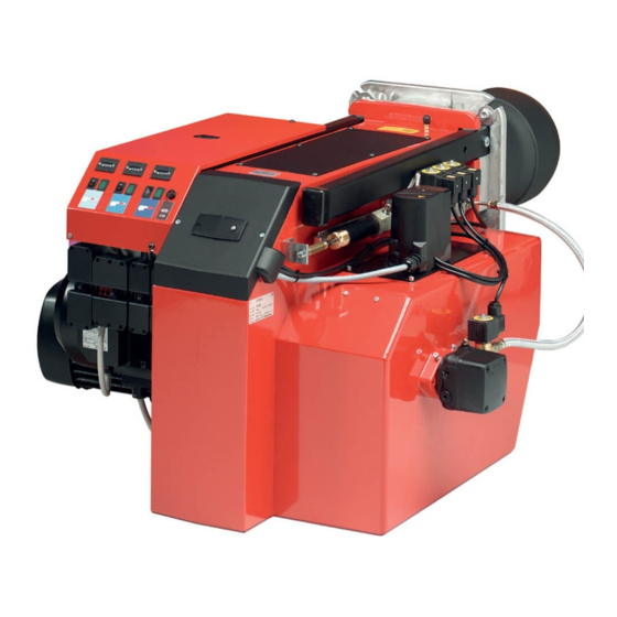
Page 12: Description
2.9 Description Inspection window Damper motor Connection box Solenoid valve Solenoids with block 10. Pump Flange 11. Insert control Burner pipe 12. Motor Flange lock 13. Fan wheel Air intake Bentone... -
Page 13: General Instructions
The system must be fine-tuned at start-up. The temperature in the chimney must be at least 60 °C at 0.5 m down in the chimney to prevent condensation. 165 105 03 Bentone... -
Page 14: Installation
4. Installation 4.1 Handling and lifting instruktion The lifting aid are available as spare parts, Bentone... -
Page 15: Acceptance Inspection
• The connection should be made in accordance with the wiring diagram. • Fuse rating is as required If any electrical connection is used other than that recommended by Bentone, there may be a danger of damage to property and personal injury. -
Page 16: Mount The Burner On The Boiler
Once the burner has been installed and commissioned, the seals of the various coupling elements should be checked (A). When a leak is detected, it is usually suffi cient to tighten the coupling element that is leaking. 165 205 98 Bentone... -
Page 17: Example Of Basic Settings
4.8 Recommended surplus air Oil type Excess air flue gases Max. % CO % CO Lambda 1.2 Light oil, B10 heating oil/ 3–5 ≈12,5 15,4 biofuel mix (as per the definition in DIN V51603-6) 165 305 07 Bentone... -
Page 18: Setting Values For Air Damper B 80
4.10 Setting values for air damper B 80 4.11 Setting values for insert B 80 Bentone... -
Page 19: Insert Control Movable Brake Disc
(XX). Read the damper angle for each of the power stages. This must then be used when the settings are made in the burner’s control system 16520598(XX) Check the air settings by conducting a fl ue gas analysis. Bentone... -
Page 20: Burner Servicing
14. Turn on the mains power. 15. Check combustion*. When soiled, always replace nozzles with new nozzles. Note: When servicing/replacing components that affect combustion, an analysis and soot test must be carried out on the installation 165 305 01 Bentone... -
Page 21: Servicing Air Dampers
Press the burner together and lock using the nuts (E). Fit the Euro plugs and turn on the mains power. Check combustion*. Note: When servicing/replacing components that affect combustion, an analysis and soot test must be carried out on the installation Bentone... -
Page 22: Replacement Of Damper Motor, Air
Connect the damper motor electrically. in the close damper Set the damper motor notches. position. If dampers Fit the Euro plugs and turn on the mains power. do engage, the auto- matic control unit will Check combustion.* report an error mes- sage. Bentone... -
Page 23: Replacing The Oil Pump
Use caution when operating the burner, surfaces may be hot. When servicing oil bearing components, check the oil leaks when the burner is commissioned after servicing. Note: When servicing/replacing components that affect combustion, an analysis and soot test must be carried out on the installation Bentone... -
Page 24: Replacement Of Electrical Components
Make sure the relay’s earth cable is in place. Turn on the mains power. Check the function of the new component. Start the burner and check the combustion. Note: When servicing/replacing components that affect combustion, an analysis and soot test must be carried out on the installation Bentone... -
Page 25: Vibration
Maximum vibration level are 5,0 mm/s • Check all bolts and nuts for correct torque • Check fan wheel for damage and contamination. Change when dirty/ unbalanced • Check motor bearings. If worn change motor/bearings Use lid screw hole for sensor mounting Bentone... -
Page 26: Instructions Pump Rsa 95 & 125
Replace the oil fiter on the oil pump as follows.. • Close the oil valves. • Unscrew the cover (4 x 5 mm Allen screws). • Replace the oil filter. • Replace the cover gasket. • Refit the cover. • Open the oil valves. 165 101 54 Bentone... -
Page 27: Function Danfoss Rsa 95 - 125
Only for capacities over 100 kg/h or on special request by customer Hydraulic control device Only on burners with hydraulic air control or nozzle assembly optimisation. Oil pump Items 3 and 6 are not fitted to two-stage burners. Item 8 is connected after solenoid valve nozzle 2 (Y2). Bentone... -
Page 28: Suction Line Tables
5 min. (a condition is that the pump is being lubricated during operation). The tables state the total suction line length in metres at a viscosity of 6,0 mm2/s. Bentone... -
Page 29: Electric Equipment
7. Electric equipment Safety system 165 305 04 Bentone... -
Page 30: List Of Components
Plug-in contact, power controller R316, burner Burner motor X10 Plug-in contact, power controller R316 Damper motor, air Solenoid valve 1 Time counter /Operation Solenoid valve 2 Operating switch Solenoid valve 3 Rules/Operating thermostat Y1S Safety solenoid valve Temperature/pressure limiter Bentone... -
Page 31: Control
LED fl ashes during start-up. In Control mode, the Status LED shines yellow, the Fan LED fl ashes, and LEDs 2-6 show the fl ame signal strength. Each LED corresponds to 20% of the total fl ame signal. 5 lit LEDs correspond to 100% and 2 LEDs correspond to 40%. 165 205 60 Bentone... -
Page 32: Explanation Of The Different Sequence Modes
Burner Lockout When lockout occurs, the LEDs indicate the cause. The control unit status is saved in the memory, even in the event of a power outage. By pressing the manual reset button on the control unit or remote reset. Bentone... -
Page 33: Burnerpro Led Fault/Lock Code Table
8.4 BurnerPro LED fault/lock code table Bentone... - Page 34 Bentone...
- Page 35 Bentone...
-
Page 36: Preface
Operating Manual B 70.3041.0 on the CD, or can be downloaded from http://www.jumo.se Scope of delivery - 1 controller - seal - mounting brackets - brief operating instructions - - 1 CD with comprehensive operating instructions and setup program as a demo version Bentone... -
Page 37: Identifying The Instrument Version
2 1 4 Math and logic module 2 1 7 Ratio controller 2 1 8 Difference controller 2 1 9 Humidity controller 703041 / 1 8 1 – 0 0 0 – 2 3 / 0 0 0 , 0 0 0 Bentone... -
Page 38: Mounting
• From the back of the panel, push the mounting frame onto the instrument body and press it against the back of the panel, compressing the springs, until the latches snap into the notches provided and it is firmly fixed in position. Bentone... -
Page 39: Electrical Connection
13. Electrical connection 13.1 Connection diagram for Type 703041 Bentone... -
Page 40: Connection Diagram For Type 703042/43/44
13.2 Connection diagram for Type 703042/43/44 Bentone... -
Page 41: Displays And Keys
- manual operation is active 16-segment display + dim. units two-digit, green; for the unit °C/°F and symbols for h, min, % Different values can also be visualized on the display. see the comprehensive operating manual on the CD Bentone... -
Page 42: Operation
Alter value with I and D The value alters dynamically with the duration of the key stroke. h Accept the setting with P or automatically after 2 sec h or h Cancel entry with X. The value is not accepted. Bentone... -
Page 43: Entering Times
Alter the output with In the case of a modulating controller, the actuator is opened or closed using the keys. The output entry on a changeover is configurable. h Return to the normal display with X (press for more than 2 seconds) Bentone... -
Page 44: Operation Of The Program Controller
Alter the present When the program is setpoint with paused, the lower display blinks. The controller controls to the present setpoint. (The value is accepted automatically after 2 sec.) The program is canceled in the event of a power failure. Bentone... -
Page 45: Operator Level „Opr
2 (with 3-state controllers) c. with dt=0, the controller has no differential action (e. g. PI controller) d. with rt=0, the controller has no integral action (e. g. PD controller) e. for controllers with Pb1/2=0 Bentone... -
Page 46: Configuration Level „Conf
3-wire circuit 2 Resistance thermometer in 8 4 — 20 mA 2-wire circuit 3 Resistance thermometer in 9 0 — 10 V 4-wire circuit 4 Thermocouple 10 2 — 10 V 5 Resistance transmitter 11 0 — 1 V Bentone... -
Page 47: Configuration Level „Conf
0 ... 1 CAct (0=direct (cooling); 1=inverse (heating)) Factory settings are shown bold. 18.2 Generator „Pro“ Generator “Pro” Parameter Symbol Value range Function Fixed-setpoint controller Fnct Ramp function Program controller Program generator Hot-channel controller Factory settings are shown bold. Bentone... -
Page 48: Utgångar „Outp
30 adressvärde (setup) 15 3. gränslarm 31 alltid „aktiv“ 18.4 Display „diSP“ Display „diSP“ Parameter Symbol Värdeområde Decimaltecken 0 ... 2 (0= ingen decimal; 1=en; 2=två)) dEcP Ljusstyrka 0 ...5 (0=ljus) Br i G Fabriksinställning visas i fet stil. Bentone... -
Page 49: Autotuning
Overrange / underrange covers the following events: - probe break / short-circuit - measurement is outside the controllable range for the probe connected - display overflow Displaying the software version h Display version with (press simultaneously). Bentone... -
Page 50: Fault Location
Preheater temperature too low Check preheater function Adjust the preheater‘s set operating tem- New oil type perature Check that the oil used has the physical parameters that the burner is rated for. If not, change the oil. 165 105 09 Bentone... -
Page 51: Delayed Ignition
Change the oil or the pump's oil parameters Pump worn Replace the pump Pump run using impure oil that has worn the Replace pump and install self-cleaning pump out prematurely filter in the oil system Blocked pump filter Check, clean pump filter Bentone... -
Page 52: Log Of Flue Gas Analysis
22. Log of flue gas analysis Owner Adresss Tel. no: Installation Tel. no: Boiler Type Make Power Bentone Burner Type Model Serial no. Fuel Step 1 Step 2 Step 3 Draught in fireplace Fan Press mbar Filter smoke number Flue gas temp. °C... -
Page 53: Oil Burners Maintenance Instructions
23. Oil burners maintenance instructions General information If the burner starts but does not ignite Keep the boiler room clean. Ensure that the boiler Make an attempt to start the burner. room has permanent fresh air intake. Switch off before Never make close repeated start attempts. - Page 56 Enertech AB. P.O Box 309, SE-341 26 Ljungby. www.bentone.se, www.bentone.com...
Need help?
Do you have a question about the B 80-3R and is the answer not in the manual?
Questions and answers