Bentone BG 550 Installation And Maintenance Instruction
Hide thumbs
Also See for BG 550:
- Installation and maintenance instruction (52 pages) ,
- Installation and maintenance instruction (52 pages) ,
- Installation and maintenance instruction (58 pages)

Related Manuals for Bentone BG 550


Summary of Contents for Bentone BG 550
- Page 1 178 034 82-3 2018-04-11 Providing sustainable energy solutions worldwide Installation- and maintenance instruction BG 550/650/700/800/950 BMS LMV Biogas...
-
Page 3: Table Of Contents
6.4 Replacement of damper motor, gas _________________________ 17. Declaration of conformity 6.5 Flame monitoring and ionisation current check ______________________________________ __________ 6.6 Gas nozzle BG 550/650 __________________________________________ 18. General instruction for gasburner ___________________________ 6.7 Gas nozzle BG 550LN ____________________________________________ 6.8 Gas nozzle BG 700/800 __________________________________________ 6.9 Gas nozzle BG 950... - Page 4 General Bentone BFG1...
-
Page 5: General Information
• Burner pipes, fan wheels and air dampers may contain sharp edges. • The surface temperature of the burner’s components can exceed 60 °C. • Caution: The burner has moving parts, and there is risk of crushing injuries. 172 515 01 2018-01-02 Bentone... -
Page 6: Actions To Take If You Smell Gas
Open windows and doors. Close the gas ball valve. Warn residents; do not use doorbells. Evacuate the building. Notify the installer or gas supplier once the building has been evacuated. 172 515 01 2018-01-02 Bentone... -
Page 7: Burner Servicing Schedule
Delivery check • Make sure everything is delivered and the goods have not been damaged during transit. • If something is wrong with a delivery, report it to the supplier. • Transport damage must be reported to the shipping company. Bentone... -
Page 8: Technical Data
Length of Flange Burner tube Burner tube Type burner tube measure A measure B measure C Standard 1 Standard 2 BG 550 Standard 3 Standard 1 BG 650 Standard 2 Standard BG 700 Långt utförande Standard BG 800 Långt utförande... - Page 9 General *590 *743 BG 550 *590 *743 BG 650 *730 *970 BG 700 *730 *1022 BG 800 *730 *1027 BG 950 * The above dimensions are max. measurements. Depending on the components used, the measurements may vary. ** Min. recommended distance to loor.
- Page 10 Nm pressure pressure mbar mbar 140–628 see data plate BG 550 140–628 see data plate BG 550 BG 550 140–628 see data plate BG 550 140–628 see data plate BG 650 200–1125...
- Page 11 General 2.2.3 Appliance categories Only dry gas is permitted for use BG 550 Gerätekategorien Versorgungsdrücke Bestimmungsländer Appliance categories Supply pressures Countries of destination 30-360mBar "BG, CZ, DE, EE, ES, FR, GR, 2R/3R HU, IS, IT, LU, LV, NO, PT, SI, All countries"...
- Page 12 LT, LU, LV, IT, NO, PT, SI, All countries” 40-360mBar ”AT, CH, CY, DK, FI, LT, RO, 2H3B/P SK” 40-360mBar GB, IE, 2H3P 40-360mBar NL, RO 2L3B/P 40-360mBar PL, RO 2E3B/P 40-360mBar 2E(R)B 40-360mBar HU, LT, LV 30-360mBar BE, HU,LT 3B/P 30-360mBar GB,LT Bentone...
- Page 13 General 2.2.4 Electric Specification Burner correspond to IP40 Type BG 550 BG 650 230/400V, 50Hz, 230/400V, 50Hz, Motor 6,5/4,0A, 1,5kW, 3,5/2,5A, 0,75kW 2890 Rpm 2860 Rpm The recommended main fuse C10A motor 230V1F~2,5A Control power 89 dBA ± 0,5 dBA 91 dBA ±...
- Page 14 General 2.2.5 Working field BG 550 140-628 kW Do not exceed working ield BG 650 200-1125 kW Do not exceed working ield 200 300 900 1000 1100 1200 Bentone...
- Page 15 Do not exceed working ield 1000 1200 1400 1600 BG 800 380-2400 kW Do not exceed working ield 1000 1200 1400 1600 1800 2000 2200 2400 BG 950 mbar 500-3200 kW Do not exceed working ield 1400 1900 2400 2900 3400 Bentone...
-
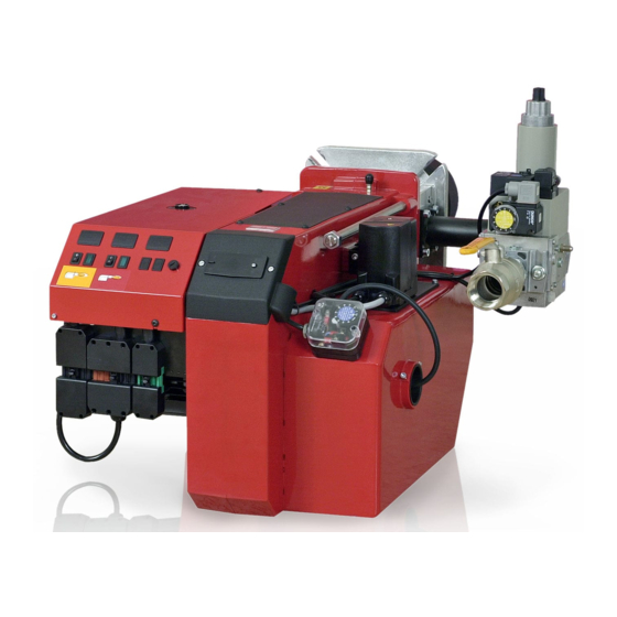
Page 16: Description Bg
General 2.3 Description BG 550/650 Bentone... - Page 17 General 2.3.1 Components BG 550/650 Burner tube Guide bar Damper motor, gas Ignition electrode Min. gas pressure switch/tightness check Shrouded disc MultiBloc Ionisation electrode Air damper Electrical connection Damper motor, air Gas nozzle Connection gas i ttings Motor Air pressure switch...
-
Page 18: Description Bg
General 2.4 Description BG 700/800/950 Bentone... - Page 19 Shrouded disc MultiBloc Ionisation electrode Air damper Electrical connection Damper motor, air Gas nozzle Connection gas ittings Motor Air pressure switch Measuring nipple, fan pressure Fan house Connection lange Sight glass AZL display for LMV automatic control unit Switch 0-l Bentone...
-
Page 20: General Instruktions
Adjust the burner to appr. 20% excess air in accordance with the table. Check the lue gas temperature. Calculate the eficiency. Check also the actual gas volume on the gas meter so that the correct input is achieved. Bentone... -
Page 21: Installation
If the boiler has a 7-pole and a 4-pole Eurostecker connector, these usually it directly to the burner. If not, use the connectors included. (Refer to connection under Electric equipment) If an electric connection other than the one recommended by Enertech is used, a risk of damage and injury can arise. Bentone... -
Page 22: Skeleton Diagrams
Valve proving system Air damper motor Air pressure switch Gas burner control LMV Pos. 5b, 7: Components not required according to EN 676. Required over 1200 kW according to EN 676 When Bio gas is used, Enertech shall always be contacted. Bentone... -
Page 23: Fitting The Burner To The Boiler
Remove the cover plate from the fan housing. Undo the nut (D) to the nozzle assembly. (applies to BG 550 & 650; does not feature on BG 700, 800 & 950) Disconnect the electrical cables to the valve assembly and gas damper motor. -
Page 24: Handling And Lifting Instruction
General 4.7 Handling and lifting instruction 4.7.1 BG 550, BG 650 Option The lifting aid we used here are available as spare parts, Figure 1 Figure 1 4.7.2 BG 700, BG 800, BG 950 Bentone... -
Page 25: Inspection Of Gas Nozzle Before Commissioning
Remove the cover plate from the fan housing. Undo the nut (D) to the nozzle assembly. (applies to BG 550 & 650; does not feature on BG 700, 800 & 950) Disconnect the ignition cable and ionisation cable for the gas nozzle. -
Page 26: Setting The Burner
5.2 Setting the air damper The position of the air damper must be adjusted to achieve a suitable fuel-air mixture in the operational events that are programmed. See section 13.4 (LMV) for the setting procedure. Bentone... -
Page 27: Setting The Gas Damper
((Q · 1,2) / 3600) ((2200 · 1,2)/3600) 5.3 Setting the gas damper The position of the gas damper must be adjusted to achieve the desired minimum and maximum input power. See section 13.4 (LMV) for the setting procedure. Bentone... - Page 28 Temperature of gas at the gas meter [°C] Barometer reading [mbar] Pressure of gas at the gas meter [mbar] Factor calculated for multiplication with low in Nm /h to arrive at actual low in Nm Actual low · 273+T 1013.25 Bentone...
-
Page 29: Calculating The Quantity Of Gas Supplied
= Time for a certain quantity of gas consumed by the burner. M = Quantity of gas consumed. V = Actual gas low Calculation example: t = 1 min 10 s M = 4500 dm (litre) 4500 4.5 m 1000 0.0194 h 3600 ≈ 232 m 0.0194 Bentone... -
Page 30: Service
Check the ionisation electrode (see chapter 11.7–11.10). Replace if necessary. Fit the combustion assembly in reverse order. Press the burner together and lock using the nuts (B). Fit the Euro plugs and turn on the main power supply. Check/adjust the combustion. Bentone... -
Page 31: Servicing Air Dampers
Lock the damper motor in position where the damper is almost engaged but still has a small air gap by the fan housing. Install the intake grille for the air intake. Press the burner together and lock using the nuts (B). Check/adjust the combustion. Bentone... -
Page 32: Replacement Of Damper Motor, Air
Install the new damper motor on the mounting plate. For BG 550/650, SQN 14 is used for air control. For BG700/800/950, SQM 33 is used. Parameter 601.00:0 Parameter 601.01:1... -
Page 33: Bg550/650
General BG700-950 BG550/650 BG550-950 Bentone... -
Page 34: Replacement Of Damper Motor, Gas
An SQN 13 damper motor must be used to adjust the gas valve. When tightening screw (Y), ensure that the damper is in the closed position. Connect the damper motor cable to the automatic control unit. Fit the Euro plugs and turn on the mains power. Check / adjust combustion. Bentone... -
Page 35: Flame Monitoring And Ionisation Current Check
Possible detector current Max. DC 16…40 µA, lame display approx. 100% Threshold values when lame is supervised by an ionization probe: - Start prevention (extraneous Intensity of lame (parameter 954) ≥18% light) - Operation Intensity of lame (parameter 954) >24% Bentone... - Page 36 General ION input ION input Ionization current in µA Ionization current in µ A Figure 1: Ionization input at AC 120 V / AC 230 V X10-05,2 Bentone...
-
Page 37: Gas Nozzle Bg 550/650
General 6.6 Gas nozzle BG 550/650 Towngas Natural gas, Propane Biogas (UV detector) 6.7 Gas nozzle BG 550LN A = 10 mm Front edge of brake plate A = Position of ionisation detector B = 3 mm B = Position of ignition electrode... -
Page 38: Gas Nozzle Bg 950
General 6.8 Gas nozzle BG 700/800 Natural gas, Propane Natural gas ≈ 15-20 Propane Biogas (UV detector) 3-3,5 10-12 Bentone... - Page 39 General 6.9 Gas nozzle BG 950 Natural gas, LPG Distance electrode - brake plate. Biogas (UV-sond) Bentone...
-
Page 40: Uv Detector
• Simultaneous operation of QRA... and ionization probe is Warning! not permitted! Threshold values when lame is supervised by QRA...: - Start prevention (extraneous light) Intensity of lame (parameter 954) ≥18% - Operation Intensity of lame (parameter 954) >24% Bentone... -
Page 41: Setting The Air Pressure Switch
This is to ensure the reliable function of the burner. If breakdowns or interruptions occur, the air pressure switch is probably set to a too narrow position. Fit the protective cover, screw (Y). Bentone... -
Page 42: Setting The Min. Gas Pressure Switch
The tolerance on the scale for the min. gas pressure switch is approx. ±15%. Open the ball valve. Remove the pressure gauge and close the pressure outlet (X). Check the gas tightness. Fit the protective cover, screw (Y). Bentone... -
Page 43: Setting The Max. Gas Pressure Switch
The tolerance on the scale for the max. gas pressure switch is approx. ±15%. Remove the pressure gauge and close the pressure outlet (X). Check the gas tightness. Fit the protective cover, screw (Y). Gas pressure switch, air pressure switch Setting range: 2.5–50 mbar 5-150 mbar Bentone... -
Page 44: Vibration
Maximum vibration level are 5,0 mm/s • Check all bolts and nuts for correct torque • Check fan wheel for damage and contamination. Change when dirty/ unbalanced • Check motor bearings. If worn change motor/bearings Use lid screw hole for sensor mounting Bentone... -
Page 45: Handing Over Of The Installation
• Has the gas control or the motor protector locked out? - Reset. • Is the circulation pump in operation? • Is there a supply of fresh air to the installation? • If integral components are of a different make from what is stated in this manual, see the enclosed loose-leaf. Bentone... -
Page 46: Regulators
For information and operation of the different regulators which can be installed directly on the burner, see the enclosed manual. When connecting an external regulator of a type other than those which are installed on burners, see the manufacturer’s recommendations and the wiring diagram for burners. Bentone... -
Page 47: Damper Motors
Max. 60 s Angular adjustment Usable range max. 90° Degree of protection IP40 Rated resolution encoder monitoring 0.7° 0-position of actuator drive shaft As supplied 0 +2° / -2° Environmental conditions: Temperature range -10...+60 °C Humidity <95 % r.h. Bentone... - Page 48 An SQN14 damper motor is used on BG 550 and BG 650 burners to control the amount of air. An SQN13 damper motor is used on BG 550, BG 650, BG 700, BG 800 and BG 950 burners to control the amount of gas.
-
Page 49: Sqm Damper Motor
Perm. on time 50%, max. 3 min. continuously Angular adjustment Usable range max. 90° Degree of protection IP40 Rated resolution encoder monitoring 0.7° 0-position of actuator drive shaft Supply state 0 ±0.6° Environmental conditions: Temperature range -20...+60 °C Humidity <95% r.h. Bentone... - Page 50 An SQN13 damper motor with anticlockwise rotation is used on BG 550 and BG 650 burners to control the amount of air. An SQN14 damper motor with clockwise rotation is used on BG 550 BG 650, BG 700, BG 800 and BG 950 burners to control the amount of gas.
-
Page 51: Gas Train
Threaded versions: DMK 512, 515 and 520 Flanged versions: DMK 5065 and 5080 DMK 5065 and 5080 Environmental conditions: Temperature range -15...70 °C Humidity <95% r.h. Gas qualities No nonferrous materials. Suited for use with gases up to max. max. 0,1 vol. % H2S, dry Bentone... - Page 52 See image • When installing a gas damper, observe the direction of low shown on the gas damper. • After working on a gas damper, check the gas tightness Bentone...
-
Page 53: Multi-Block Vgd40
Degree of protection IP54 Multi-block connection lange VGD40.65/SKP15/25 DN65 VGD40.80/SKP15/25 DN80 Environmental conditions: Temperature range -10...60 °C Humidity <95% r.h. Gas qualities No nonferrous materials. Suited for use with gases up to max. max 0,1 vol. % H2S, dry Bentone... - Page 54 The burner can also be i tted with an additional gas pressure switch to monitor that the nozzle pressure does not get too high. Bentone...
- Page 55 Pa, see image. Turning to right = higher regulator pressure Turning to left = lower regulator pressure Fit protective plug X. Possible output pressure range 15–120 mbar. Pressure is measured at the pressure outlet on SKP25. See section 10.2.2. Bentone...
- Page 56 > 4 mm. The impulse pipe must be protected again breakage and damage. If damage should occur, the impulse pipe must be replaced before the burner is put into operation again. Bentone...
- Page 57 1, 2, 3, 5 Sealing plug 6, 7 G 1/4 8, 9 G 1/2 Option Screw plugs 1,2,3 ,5may also be replaced by a measuring socket G 1/8 DIN ISO 228. Concealed connecting bore for system accessories. 172 515 83 2018-04-05 Bentone...
- Page 58 3 in 1.5mm cap stand headed screw. After setting the requested pressure setpoint: Close protective valve 1. Route wire through 2 and 3, Fig. 2. ° ° Vmin. / mini.> 0.1 x Vmax. / maxi. Press lead around wire ends, keep wire loop short. Bentone...
- Page 59 1 - 5. Replace solenoid Important: Make sure that the solenoid no. and voltage are correct! Remount hydraulic brake or adjust-ing plate as described on. ”Replacing the hydraulic brake or adjusting plate”, steps 7 -11. Bentone...
- Page 60 Max. operating pressure 500 mbar Pressure regulator Class A Ambient temperature -15 °C … +70 °C Inlet pressure range 5 - 500 mbar Family 1 + 2 + 3 Outlet pressure range 2,5 - 200 mbar Bentone...
- Page 61 FRS 525 083 303 500 Rp 22 230 6,00 FRS 5065 058 792 500 DN65 7,50 FRS 5080 079 681 500 DN80 10,00 Do not use unit as lever. 21/2 1100 1600 2400 5000 6000 7600 (Nm) < (Nm) < Bentone...
- Page 62 Turn spindle to stop. Unscrew complete adjustment device B and remove spring C. Insert new spring D. Assemble complete adjustment device and adjust desired off-set. Screw on protective cap A. Stick adhesive label E onto typeplate. Attach lead seal. Bentone...
-
Page 63: Electric Equipment
• The high gas pressure switch can be installed to the connection pipe between the multi-block and the burner head, and will then function as a power monitor. • Installation will block burner operation and a manual restart will be required. Installation must be carried out pursuant to applicable regulations. Bentone... -
Page 64: Wiring Diagram
General 13.2 Wiring diagram Bentone... -
Page 65: Wiring Diagram Rwf 50:3
General 13.3 Wiring diagram RWF 50:3 Bentone... -
Page 66: Wiring Diagram Rwf 50:2
General 13.4 Wiring diagram RWF 50:2 Bentone... -
Page 67: Wiring Diagram Jumo 316
General 13.5 Wiring diagram Jumo 316 Bentone... -
Page 68: List Of Components
Contact for damper motor, air SQM 33 (BG700-950) Contact for damper motor, gas SQN 13 AZL display for LMV automatic control unit Contactor with surge protection Transformer Fuse holder Branching point/measuring point for ionisation LMV automatic control unit Quick-release switch for regulator Bentone... -
Page 69: Lmv37 Automatic Control Unit
Example: Modulating gas burner The system components (display and operating unit, actuators) are connected directly to the LMV37.4... basic unit. All safety-related digital inputs and outputs of the system are monitored by a contact feedback network. Bentone... -
Page 70: General Information
6.3 AT (DIN EN 60127 2 / 5) Mains supply: Input current depending on the operating state of the unit Under voltage Safety shutdown from operating position at mains voltage LMV37.400A2 Approx. AC 186 V Restart on rise in mains voltage LMV37.400A2 Approx. AC 195 V Bentone... - Page 71 X5-02 pin 2/3 POC *) RAST plug Function / Outputs pin number X3-05 pin 1 X4-02 pin 2/3 X6-03 pin 2/3 X8-02 pin 1/3 X7-01 pin 2/3 X7-02 pin 2/3 X3-05 pin 2 0° 0° 0° Legend to the sequence diagrams Bentone...
- Page 72 Postpurge time (t3) Evacuation of test space Atmospheric pressure test Filling of test space Gas pressure test Gas shortage waiting time Valve proving is performed depending on the parameter settings: Simultaneously with the prepurge time and/or the afterburn time. Bentone...
- Page 73 Only with fuel train Lo and 2 fuel valves Parameter 223: Repetition limit value gas pressure switch-min in connection with gas shortage program parameter 246 (phase 90) Max. drop-in/response time for air pressure switch Alternative to valve proving Alternative to pressure switch-max (Pmax) or POC Bentone...
- Page 74 0°/10% Position as supplied (0°) 90°/100% Actuator fully open (90°) Input/output signal 1 (ON) Input/output signal 0 (OFF) Input permissible signal 1 (ON) or 0 (OFF) Bentone...
-
Page 75: Connection And Internal Diagram
Protection earth (PE) Supply for fuel meter Shielding: Input fuel meter For shielding the cables on the VSD, refer to: • Siemens SED2 VSD Commissioning Manual (G5192), chapters 4 and 7, or • Danfoss Operation Manual VLT 6000 (MG60A703), chapter Installation Bentone... - Page 76 Speed feedback signal Speed feedback signal Signal reference PWM speed output PWM speed output Signal reference DC 24 V external DC 24V external Controller input 4...20 mA Controller input 4...20 mA Power source Power source Controller Analog Analog Controller Bentone...
-
Page 77: Operation
• For changing to a higher menu level (press button for 3…8 s) • For changing the operating mode (press button for >8 s) /reset - Enter in parameter setting mode - Reset in the event of fault - One menu level down Bentone... - Page 78 Figure 4: Meaning of display Fault status message Flame present Valve controlled Ignition controlled Fan motor controlled Oil preheater on Heat request from controllers Parameter setting mode Info mode Service mode h min s Actuator closing Actuator opening Unit of current display Bentone...
-
Page 79: List Of Phase Displays
Postpurge time (t3) (abortion when load controller ON) Ph80 Valve proving test evacuation time Ph81 Valve proving test time atmospheric pressure, atmospheric test Ph82 Valve proving illing test, illing Ph83 Valve proving time gas pressure, pressure test Ph90 Gas shortage waiting time Bentone... -
Page 80: Automatic Control Unit Levels
Change to normal Change to normal display display >3 s <8 s Info level /reset >3 s <8 s /reset or automatic return after timeout of Service level menu operation (parameter 127) >8 s >1 s Parameter level Parameter level Bentone... - Page 81 Basic unit Air-fuel ratio control curves (primary setting) /reset Bild 388e/1109 /reset Air-fuel ratio control /reset The following sections explain the Actuator operating philosophy behind the parameter levels using a number of examples. /reset Error histery /reset Process data Bentone...
- Page 82 Standardized speed Number of faults Error history: 701-725.01.Code 701. chronological error list index value of index Indexlista: 04 = error phase 01 = error code 05 = startup counter 02 = diagnostic code 06 = output 03 = error class Bentone...
- Page 83 The code for logging into service level is found on the plate on the inside of the cover for the electrical connections box. Press button combination to display CodE When releasing the buttons, 7 bars appear the irst of whishes. h min s Press to select a number or letter. h min s Press to conirm the value /reset Bentone...
- Page 84 The next bar starts lashing. h min s Complete the rest of the password according to the principle described. Example: Password consisting of 4 characters. min s After entery of the last character the password must be conirmed by pressing /reset Bentone...
-
Page 85: Setting The Automatic Control Unit
400 for initial commissioning and for setting air-fuel controll. /reset 201: appears l ashing. h min s Press to go to the settings for air-fuel ratio control and parameter /reset 201 for selecting the operating mode. Bentone... - Page 86 20 = gas modulating with pilot only when iring on gas (Gp1 mod fuel active) • 21 = gas modulating with pilot only when iring on gas (Gp2 mod fuel active) • 22 = oil modulating only when iring on oil (Lo mod fuel active) • Bentone...
- Page 87 Select your setting by pressing one of the buttons Press to save the setting for parameter 542: VSD /reset This manual describes “0=VSD OFF” type burners. Press: to return to parameter level. To the next parameter Back to the previous parameter Bentone...
- Page 88 Press simultaneously to set ignition position P0 of the fuel damper. Set a suitable fuel-air mixture so that the burner starts. Example: 30.0 h min s Press simultaneously to set ignition position P0 of the air actuator. Bentone...
- Page 89 To the next curvepoint P9 appears lashing. Curvepoint for high-ire. Same procedure as with P0 h min s Note: is pressed irst, the display jumps to 90! Back to the previous curvepoint When curvepoint 9 is set, press to start the burner. Bentone...
- Page 90 This method makes the setting work easier and faster to complete. A more “correct” setting is obtained straight away. The process may need to be redone if the wrong input power was set for P9 initially. For this reason, be extremely careful when entering the irst setting of P9. Bentone...
- Page 91 Phase Fan ramp up (fan motor = ON, safety valve = ON) h min s Phase Traveling to prepurge position h min s Phase Prepurging h min s Phase Traveling to ignition position h min s Bentone...
- Page 92 Phase Traveling to ignition position h min s Phase Preignition h min s Phase for irst safety time (ignition transformer ON) h min s Phase for irst safety time (ignition transformer OFF), preignition time OFF h min s Phase Interval 1 min s Bentone...
- Page 93 Low lame position P1 can only be set when symbol is no longer highlighted. The value is adopted from P0 For fuel, keep depressed, for air h min s press to adjust the value. When symbol is no longer highlighted. Bentone...
- Page 94 The setting curve is therefore adjusted to the highest input power that the installation can handle. The desired input power is then set by entering how much of the maximum power is required. Bentone...
- Page 95 When symbol or is no longer highlighted, you can press ESC a second time. h min s Press to exit parameter level. h min s The settings for air-fuel ratio control by the LMV37.4... are now completed. Bentone...
- Page 96 0 = QRB / QRC 1 = ION / QRA Factory settings marked with bald text. When replacing detector lame between ionisation and UV-cell (QRA), no change to the setting parameters is required; simply disconnect and connect ionisation and UV-cell (QRA) respectively.. Bentone...
- Page 97 1 = active (postpurge position) Factory settings marked with bald text. When the Purging in the lockout position function is used, the fan may only be powered via a contactor and must not be connected directly to LMV37.4 (X3-05 pin 1)! Bentone...
- Page 98 23 hours and 45 min of uninterrupted operation, followed by an automatic restart. When forced intermittent operation is inactivated the burner will run continuously. Forced intermittent operation is a standard feature. 239 Gas: Forced intermittent operation 0 = inactivate 1 = activated Factory settings marked with bald text. Bentone...
- Page 99 After login is complete, continue with the setting work as shown below. h min s Press to select parameter 400 for initial commissioning and for setting air-fuel ratio control /reset Identii cation of start for setting the curve parameters. h min s Bentone...
- Page 100 The value is adopted from P0. For fuel, keep depressed, for air Press to adjust the value. h min s When symbol is no longer highlighted, the next curvepoint P2 can be selected with To the next curvepoint back to the previous curvepoint Bentone...
- Page 101 If required, readjust the gas pressure. For fuel, keep depressed, for air h min s Press to adjust the value. When symbol is no longer highlighted, the curve is set and it is possible to go on with the rest of the setting. Bentone...
- Page 102 /reset maximum capacity. Adjust the setting downwards or upwards using the buttons h min s Press to save the setting. /reset Press to return to parameter level. To the next parameter. Bentone...
- Page 103 Back to the previous Completing parameter parameterization of the curve When symbol is no longer highlighted, you can press ESC a second time. h min s h min s The warm settings for air-fuel ratio control by the LMV37.4... are now completed. Bentone...
-
Page 104: Backup And Restore
To continue with the setting work, you need to log into service engineer level. See 5.3.4. After login is complete, continue with the setting work as shown below. Press for parameter level 000. Press /reset Display: Parameter 050, lashes, index 00, and value 0 do not. /reset Display: Parameter bAC_UP /reset Bentone... - Page 105 If an errror occurs during the backup process, a negativ value is displayed. For error diagnostics, the cause of the error can be determined from the diagnostic code of error message 137 (see Error code list) Press four times until the top menu is displayed. Bentone...
- Page 106 After login is complete, continue with the setting work as shown below. Press for parameter level 000. Press /reset Display: Parameter 050, lashes, index 00, and value 0 do not. /reset Display: Parameter bAC_UP Press to select parameter rESstorE /reset Bentone...
- Page 107 Press to select the restore process. /reset Press to shift the value in change mode 1 position to the left. Display: Value 1 lashes To detect potential dispalay errors, the value is displayed 1 place shifted to the left Bentone...
-
Page 108: Fault Status Message, Display Of Errors And Info
The display shows current error code c: alternating with diagnostic code d: (refer to Flash code list). Example: Error code 4/diagnostic code 3 h min s When pressing for 1...3 s, rESEt appears on the display. /reset Bentone... - Page 109 SEr and then OPErAtE. >5 s For a list of parameters, see table 5.3.3. /reset h min s When the button is released, a change to info / service mode is made. >8 s /reset h min s Bentone...
- Page 110 The unit initiates safety shutdown. The display shows current error code c: alternating with diagnostic code d:. h min s Press 1...3 s, to return to the normal display. /reset Example: Error code 12 / diagnostic code 0 h min s Bentone...
- Page 111 Display: Parameter 701. lashes, index 01: and example value 201 does not. h min s Press to go to index 01: /reset Display: Parameter 701. does not lash, index 01: lashes, value 201 does not. h min s To the next index Back to the previous index. Bentone...
- Page 112 /reset Press to go to display mode. /reset Display: Value 56 (number of startup) h min s Press to return to the index. Display: Parameter 701. does not lash, index 05: lashes, characters ._._ h min s do not. Bentone...
- Page 113 To the next index Back to the previous index. When this display appears, you have reached the end of the error history. Display – End – appears lashing. h min s Press twice. HISt 700: for error history h min s Bentone...
-
Page 114: Dispaly Message Of Info
OFF UPr. h min s 15.7.3 Safety loop A unit whose safety loop and / or burner lange contact is open, and a controller ON signal is present, displays OFF S. h min s Bentone... -
Page 115: Resetting The Automatic Control Unit
Select another burner type than the one already selected by pressing one of the buttons Conirm this selection with The automatic control unit is now reset. /reset h min s Restart the setting process for the LMV automatic control unit as speciied in 3.2.1. Bentone... -
Page 116: Manual Output
LoAd 0.0 means Manually OFF. As long as the Manual OFF is active, OFF appears on the normal display lashing. To deactivate and to change to automatic operation, press for 3 seconds. Then OFF appears without lashing in the display. Bentone... - Page 117 Manually OFF must not be used just to put a burner out of operation when doing mounting work, or when the burner is not ready for operation. The safety notes contained in chapter Safety notes must be observed! Bentone...
- Page 118 16. Parameter list Num- Par. ber of Default Value range Resolu- Password Parameter ele- Type Edit setting tion level ments Internal parameters Start backup / restore via AZL2.../ PC software (set parameter to 1) Index 0: Create backup Std_s8 edit 0;...
- Page 119 Num- Par. ber of Default Value range Resolu- Password Parameter ele- Type Edit setting tion level ments Mains frequency LMV37.400...: 0 0 = 50 Hz Selection edit LMV37.420...: 1 1 = 60 Hz Display brightness LMV37.400...: 75 % Std_u8 edit 100% LMV37.420...: 100 % Fuel meter: Pulse valency [pulses / volume unit]...
- Page 120 Num- Par. ber of Default Value range Resolu- Password Parameter ele- Type Edit setting tion level ments Default output if communication with building automation is interrupted Setting values: For modulation operation the setting range is as follows: 0…19.9 = burner off 20…100 = 20…100% burner rating Output edit / clear...
- Page 121 Num- Par. ber of Default Value range Resolu- Password Parameter ele- Type Edit setting tion level ments Burner operating mode (fuel train, modulating / multistage, actuators, etc.) -- = undefined (delete curves) 1 = G mod 2 = Gp1 mod 3 = Gp2 mod 4 = Lo mod 5 = Lo 2-stage...
- Page 122 Num- Par. ber of Default Value range Resolu- Password Parameter ele- Type Edit setting tion level ments Fan ramp up time Time edit 60 s 0.2 s Max. time down to low-fire Time edit 0.2 s 10 min 0.2 s 45 s Repetition limit safety loop 1 = no repetition...
- Page 123 Num- Par. ber of Default Value range Resolu- Password Parameter ele- Type Edit setting tion level ments Gas: Pressure switch-max / POC input 0 = inactive LMV37.400...: 1 1 = pressure switch-max Selection edit LMV37.420...: 2 2 = POC 3 = pressure switch valve proving Gas: Forced intermittent operation 0 = inactive Selection...
- Page 124 Num- Par. ber of Default Value range Resolu- Password Parameter ele- Type Edit setting tion level ments Ramp modulating Std_u8 edit 32 s 80 s 32 s Lower output limit Output edit / clear 100% 0.1% undefined SO (BA) undefined = 20 % Upper output limit Output edit / clear...
- Page 125 Num- Par. ber of Default Value range Resolu- Password Parameter ele- Type Edit setting tion level ments Standardized speed Index 0 = speed 1 Std_u16 read only 6500 undefined Index 1 = speed 2 (internal supervision) Configuration of analog output 0 = DC 0...10 V Std_u8 edit...
- Page 126 Num- Par. ber of Default Value range Resolu- Password Parameter ele- Type Edit setting tion level ments Result of contact sensing (bit-coded) Bit 0.0 = 1: Pressure switch-min Bit 0.1 = 2: Pressure switch-max Bit 0.2 = 4: Pressure switch valve proving Bit 0.3 = 8: Pressure switch air pressure switch Bit 0.4 = 16: Load controller OPEN Bit 0.5 = 32: Load controller ON...
-
Page 127: Error Code List
17. Error code list Error code Diagnostic code Meaning for the LMV37.4... system Remedy no Comm No communication between LMV37.4... basic unit and AZL2... Check wiring for line interruption/loose contact No flame at the end of the safety time (TSA) No flame at the end of safety time 1 (TSA1) No flame at the end of safety time 2 (TSA2) No flame at the end of safety time 1 (TSA1) (software version... - Page 128 Error code Diagnostic code Meaning for the LMV37.4... system Remedy Loss of flame Loss of flame Loss of flame (software version ≤ V02.00) 3...255 Loss of flame due to TÜV test (loss-of-flame test) Valve proving Fuel valve 1 (V1) leaking For valve proving via X5-01 (gas pressure switch-min) (fuel valve 2 with valve proving via X5-01) - Check to see if the valve on the burner side is leaking...
- Page 129 Error code Diagnostic code Meaning for the LMV37.4... system Remedy Pressure switch-max (Pmax) / POC Pressure switch-max (Pmax): Max. gas / oil pressure exceeded Check wiring to see if there is a line interruption. POC: POC open (software version ≤ V02.00) POC: Check to see if the valve’s closing contact is closed.
- Page 130 Error code Diagnostic code Meaning for the LMV37.4... system Remedy Internal error Make a reset; if error occurs repeatedly, replace the unit Internal error Make a reset; if error occurs repeatedly, replace the unit Internal error Make a reset; if error occurs repeatedly, replace the unit Internal error Make a reset;...
- Page 131 Error code Diagnostic code Meaning for the LMV37.4... system Remedy Control range limitation of VSD Basic unit could not correct the difference in speed and reached a control range limit. 1. Basic unit is not standardized for this motor repeat standardization. Caution! Settings of air-fuel ratio control must be checked!
- Page 132 Error code Diagnostic code Meaning for the LMV37.4... system Remedy Speed variation / VSD ramp up time too long / speed below Motor has not reached a stable speed after ramp up. minimum limit for standardization 1. Ramp time settings of the VSD are not shorter than those of the basic unit (parameters 522, 523).
- Page 133 Error code Diagnostic code Meaning for the LMV37.4... system Remedy Running command with no preceding standardization VSD is controlled but not standardized make standardization No standardized speed available Motor turns but is not standardized make standardization Speed error VSD Required speed has not been reached Bit 0 Lower control range limitation Speed has not been reached because control range limitation has become...
- Page 134 Error code Diagnostic code Meaning for the LMV37.4... system Remedy Curve slope actuators Bit 0 VSD: Curve too steep in terms of ramp speed Check speed differential between the curvepoints and the modulating operating Valency 1 ramp setting (parameter 544). 1.
- Page 135 Error code Diagnostic code Meaning for the LMV37.4... system Remedy Error fuel actuator Position error Target position could not be reached within the required tolerance band check to see if actuator is locked or overloaded Bit 0 Line interruption Line interruption detected at actuator’s terminals Valency 1 check wiring (voltage X54 across pin 5 or 6 and pin 2 >0.5 V) Bit 3...
- Page 136 Error code Diagnostic code Meaning for the LMV37.4... system Remedy Short-circuit of sensor Short-circuit at QRB... 1. Check wiring. 2. Flame detector possibly fault Error relay supervision 3 Ignition transformer External power supply active contact Check wiring 4 Fuel valve 1 5 Fuel valve 2 6 Fuel valve 3 Error relay supervision...
- Page 137 Error code Diagnostic code Meaning for the LMV37.4... system Remedy Internal error relay control Make a reset. If error occurs repeatedly, replace the unit Software version V03.10: If error C:99 D:3 occurs during standardization of the VSD, deactivate temporarily function Alarm in case of start prevention (parameter 210 = 0, when using a release contact) or interrupt the controller-ON signal Internal error relay control...
- Page 138 Error code Diagnostic code Meaning for the LMV37.4... system Remedy Internal error EEPROM access Make a reset, repeat last parameterization / check. Restore the parameter set, if error occurs repeatedly, replace the unit Internal error EEPROM access Make a reset, repeat last parameterization / check. Restore the parameter set, if error occurs repeatedly, replace the unit Internal error EEPROM access Make a reset, repeat last parameterization / check.
- Page 139 Error code Diagnostic code Meaning for the LMV37.4... system Remedy 242 (-14) Backup – backup made is inconsistent Backup is faulty and cannot be transferred back 243 (-13) Backup – data comparison between µCs faulty Repeat reset and backup 244 (-12) Backup data are incompatible Backup data are incompatible with the current software version, restore not possible...
- Page 140 Error code Diagnostic code Meaning for the LMV37.4... system Remedy Manual locking by the PC software During a curve adjustment via the ACS410, communication between the Communication breakdown LMV37.4... and the ACS410 was interrupted for more than 30 seconds Manual locking after PC software PC software made a reset attempt although the system worked correctly reset attempt Internal error management...
-
Page 142: General Instruction For Gasburner
19. General instruction for gasburner General instructions for gasburners Installation Follow standards and instructions applicable to the Check that the input pressure of the gas is correct installation of gas burners Check that the dampers of the boiler are open Ensure that the electric installation is made in Check that there is water in the system accordance with existing regulations... - Page 148 Enertech AB. P.O Box 309, SE-341 26 Ljungby. www.bentone.se, www.bentone.com...
Need help?
Do you have a question about the BG 550 and is the answer not in the manual?
Questions and answers