Bentone BG 400 Manual
Hide thumbs
Also See for BG 400:
- Installation and maintenance instruction (48 pages) ,
- Manual (25 pages) ,
- Installation and maintenance instruction (58 pages)

Subscribe to Our Youtube Channel
Related Manuals for Bentone BG 400


Summary of Contents for Bentone BG 400
- Page 1 CR00264 178 043 73-2 2021-06-11 Providing sustainable energy solutions worldwide Installation- and maintenance instruction BG 400 LME21.550C2 MB-DLE412 Translation of the original instructions.
- Page 2 1~230V 1,0A 50Hz IP 20 Motor supply MADE IN SWEDEN BY 1. Manualer på övriga språk 1. Manuals in other languages 1. Manualer på andre sprog 2. www.bentone.com\ 2. www.bentone.com\download 2. www.bentone.com\download nedladdning or scan QR-code. eller scan QR-koden. eller scanna QR-koden.
-
Page 3: Table Of Contents
Burners are intended for use at: _________________________ 7 6.7 Recommended excess air when using default setting __ 26 2.1 Dimensions BG 400 _______________________________ 7 6.8 Determining the gas quantity for the system __________ 26 2.3 Gas categories, approved gases ____________________ 8 6.9 Calculating the quantity of gas supplied _____________ 28... -
Page 4: General Information
• Burner pipes, fan wheels and air dampers may contain sharp edges. • The surface temperature of the burner’s components can exceed 60 °C. • Caution: The burner has moving parts, and there is risk of crushing injuries. 172 515 01 2018-01-02 Bentone... -
Page 5: Actions To Take If You Smell Gas
Open windows and doors. Close the gas ball valve. Warn residents; do not use doorbells. Evacuate the building. Notify the installer or gas supplier once the building has been evacuated. Bentone... -
Page 6: Burner Servicing Schedule
Delivery check • Make sure everything is delivered and the goods have not been damaged during transit. • If something is wrong with a delivery, report it to the supplier. • Transport damage must be reported to the shipping company. Bentone... -
Page 7: Technical Data
2. Technical Data Burners are intended for use at: • Hotwater in intermittent operation. 2.1 Dimensions BG 400 • Gas connections 1” Length of Flange Type burner tube measure A Standard 1 Standard 2 BG 400 Standard 3 * Depending on which components that are used, dimensions may vary Ø... -
Page 8: Gas Categories, Approved Gases
Gas quantity Gas quantity Max. Min connection at min. power at max. power connection pressure mbar pressure mbar BG 400 G20 61-320 33,7 G25 61-320 39,0 see data plate G30 61-340 10,5 G31 61-340 13,8 ) Lower heat value Hu at normal state 15°C and 1013.25 mbar EN676... -
Page 9: Working Field
G30, G31 61-340 kW Do not exceed working field. 2.5 Electric Specification EN 60335-2-102 Burner correspond to IP20 Type BG 400 Motor supply 250W 230V 1,7A 50Hz The recommended main fuse C10A motor Main supply 230V 2,2A 50Hz Sound 85 dBA ±... -
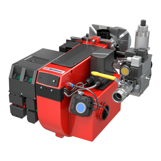
Page 10: Description
Air pressure switch Air intake Ignition electrode Air adjustment Gas pressure switch Transformer Inner assembly adjustment Ball valve Ionization electrode (not town gas) Control box Inner assembly Multibloc Electrical connection Nozzle Flame cone Reset button Brake plate Connecting pipe Fan wheel Bentone... -
Page 11: General Instructions
Adjust the burner to appr. 20% excess air in accordance with the table. Check the flue gas temperature. Calculate the efficiency. Check also the actual gas volume on the gas meter so that the correct input is achieved. 172 515 03-2 Bentone... -
Page 12: Installation
(see Basic settings). Note that it is only a basic setting which should be adjusted once the burner has been started. If an electric connection other than the one recommended by Enertech is used, a risk of damage and injury can arise. 172 515 03-2 Bentone... -
Page 13: Mounting On The Boiler
Connect the gas to the burner by means of the ball valve. Ensure that the union nut, ball valve and tubing make it easy to remove the burner for inspection and service. Check the gas tightness. 172 515 06 2018-01-02 Bentone... -
Page 14: Inspection Of Gas Nozzle Before Commissioning
At the end of the safety time (2-3 sec.) the gas control locks out. The solenoid valve and the motor will be "dead". Remove the link from the gas pressure switch after the test is finished. 172 515 07 2018-01-02 Bentone... -
Page 15: Gas Nozzle
4.8 Gas nozzle Natural gas Propane Biogas (UV detector) 172 515 07 2018-01-02 Bentone... -
Page 16: Setting The Burner
Loosen the nuts a. Swing out the burner. Remove the screw b and the knob for adjustment of burner head. Loosen the screw c so much so that the inner assembly can be pulled out. Control of burner head 172 515 09 Bentone... - Page 17 Gas quality max. CO lambda 1,2 Open the ball valve and switch on the main switch. If the Natural gas 10,0 4±1 11,9 burner starts the actual adjustment can be made. 11,5 4±1 13,9 172 515 09 Bentone...
-
Page 18: Setting The Air Pressure Switch
This is to ensure the reliable function of the burner. If breakdowns or interruptions occur, the air pressure switch is probably set to a too narrow position. Fit the protective cover, screw (Y). 172 515 09 Bentone... -
Page 19: Setting The Min. Gas Pressure Switch
The tolerance on the scale for the min. gas pressure switch is approx. ±15%. Open the ball valve. Remove the pressure gauge and close the pressure outlet (X). Check the gas tightness. Fit the protective cover, screw (Y). 172 515 09 Bentone... -
Page 20: Skeleton Diagram Cpi
Gas pressure switch, maxi Main valve Safety valve Valve proving system Air pressure switch Electrical connection Solenoid V3 Pos. 5b, 7: Components not required according to EN 676. Required over 1200 kW according to EN 676. 172 525 15 2020-10-08 Bentone... -
Page 21: Multi-Bloc
(DIN EN 175 301-803 connector) (option) Outlet flange Test point connection G 1/8 upstream of V1, possible on both sides Test point connection M4 downstream of valve 2 Gas flow direction 172 525 14 2020-10-16 /1 Bentone... -
Page 22: Mounting Closed Position Indicator (Cpi)
Then rotate the setting screw by another scale division. Check function by activating the valve. Re-set switching point Turn setting screw C back in arrow direction ”–” to the stop; proceed as described in 7. 172 525 14 2020-10-16 /2 Bentone... -
Page 23: Adjustment Of Governor
At small capacities (gas flows) it is also necessary to adjust as above. Flow adjustment Adjustment of V2 damper e:under cap 172 525 14 2020-10-16 /3 Bentone... -
Page 24: Skeleton Diagrams
6.6 Skeleton diagrams 6.6.1 Multi-bloc MBD-LE..B07 Filter cover p Br 1,3,4,6 G 1/8 screw plug Test nipple (option) M4 screwed sealing plug p Br 5 3 4 6.6.2 Electritrical connection MBD-LE..B07 MB-D(LE) B07 S22 / S52 172 525 14 2020-10-16 /4 Bentone... - Page 25 E on the working diaphragm 26 of the regulator. In regulated state, setting spring inlet pressure and pressure of working diaphragm are in force equilibrium. The compensating diaphragm ensures the fast closing function of valve V1 and a high regulating quality. 172 525 14 2020-10-16 /5 Bentone...
-
Page 26: Recommended Excess Air When Using Default Setting
Lower heat value Hu at normal state 15°C and 1013.25 mbar EN676 Grade of gas kWh/Nm MJ/Nm kcal/Nm Natural gas 34.02 8126 Natural gas 29.25 6986 Butane 32.5 116.09 27728 Propane 24.6 88.00 21019 Biogas 21,60 5159 172 515 13 Bentone... - Page 27 Temperature of gas at the gas meter [°C] Barometer reading [mbar] Pressure of gas at the gas meter [mbar] Factor calculated for multiplication with flow in Nm /h to arrive at actual flow in Nm Actual flow · 273+T 1013.25 Bentone...
-
Page 28: Calculating The Quantity Of Gas Supplied
= Time for a certain quantity of gas consumed by the burner. M = Quantity of gas consumed. V = Actual gas flow Calculation example: t = 1 min 10 s M = 330 dm (litre) 0.33 m 1000 0.0194 h 3600 0,33 ≈ 17 m 0.0194 Bentone... -
Page 29: Service
Check the ionisation electrode (see chapter Gas nozzle). Replace if necessary. Fit the combustion assembly in reverse order. Press the burner together and lock using the nuts (B). Fit the Euro plugs and turn on the main power supply. Check/adjust the combustion. 172 615 01 2018-01-02 Bentone... -
Page 30: Servicing Air Dampers
Turn the damper and then lift up the damper and damper plate. Clean the air damper and intake. Lubricate the damper shaft, if so equipped. Refit the damper and damper plate. Adjust the damper before tightening the screws (d). Install the intake grille for the air intake. Check/adjust the combustion. Bentone... -
Page 31: Flame Monitoring And Ionisation Current Check
Required current to ensure detection Min. DC 3 µA Possible detection current Max. DC 20 µA Operational indicator lamp flashes green <5 µA DC Operational indicator lamp shines green >5 µA DC 7.3.1 Flame monitoring ionisation 172 615 02-2 Bentone... - Page 32 Max. current for flame detection Max. DC 5.5 µA Required current to ensure detection Min. DC 40 µA Possible detection current Max. DC 60 µA Operational indicator lamp flashes green <45 µA DC Operational indicator lamp shines green >45 µA DC Bentone...
-
Page 33: Handing Over Of The Installation
• Is the circulation pump in operation? • Is there a supply of fresh air to the installation? • If integral components are of a different make from what is stated in this manual, see the enclosed loose-leaf. 172 615 04 Bentone... -
Page 34: Electric Equipment
Signals must be in different harnesses for safety reasons. Safety system as door switches, water level, pressure, temperature and other safety limiters must be installed in safety loop according to process. 172 615 76 2020-10-16 /1 Bentone... -
Page 35: Wiring Diagram Lme
10.1 Wiring diagram LME... 172 615 76 2020-10-16 /2 Bentone... -
Page 36: Function Lme
< 1 s < 1 s Reaction time on fl ame failure < 1 s < 1 s Min. ionisation current at fl ame 5 µA 5 µA Max. ionisation current 20 µA 20 µA 172 615 76 2020-10-16 /3 Bentone... -
Page 37: Control Program When Disruption
7.2.1.2 Limiting of starting repetitions LME ... has a function with start repetition if the flame is not created at start ord disappears during operation.. LME ... allows max. three repetitions during coninuous starting cycle 172 615 76 2020-10-16 /4 Bentone... - Page 38 3 s. To return to normal mode, hold the reset button depressed for more than 3 s. If the firing unit is in the alarm mode, it is reset by pressing the reset button 0.5...3 s. 172 615 76 2020-10-16 /5 Bentone...
-
Page 39: Troubleshooting
Burner control faulty Replace Air pressure gauge incorrectly set or faulty Check the settings and reset, or replace No acknowledgement signal due to incorrect adjustment or Check the settings and realign. misalignment of the control motor cams. 172 615 06 2018-01-10 Bentone... - Page 40 Poor draught conditions. Check the chimney. Flue gas temperature too high. Boiler overloaded Decrease the gas volume, sweep the chimney if necessary. content too low. Choke the air supply. Check the boiler for any leakages. Choke the draught if too high. Bentone...
- Page 41 Flame at incorrect angle due to combustion head out of position. Check the combustion head and readjust. Condensation build up in boiler and chimney: Flue gas temperature too low or gas volume too low. Raise the flue gas temperature by increasing gas volume Insulate the chimney. Bentone...
-
Page 42: General Instructions For Gasburners
12. General instructions for gasburners 12.3.1 Installation Follow standards and instructions applicable to the Check that the burner is adapted to the gas quality in installation of gas burners. question. Ensure that the electric installation is made in accordance Check that the input pressure of the gas is correct. with existing regulations. -
Page 43: Service- And Inspection Card
Service- and inspection card Installation Boiler Name: Type: Efficiency kW: Address: Burner Type: Efficiency kW: Installed by: Date: Date gas/h Governor Fluegas Ionisation Pressure Efficiency temp current Fire Chimney room Measu- rement Before After °C µ A mbar mbar Small Flame Large Flame... - Page 48 Enertech AB. P.O Box 309, SE-341 26 Ljungby. www.bentone.com...
Need help?
Do you have a question about the BG 400 and is the answer not in the manual?
Questions and answers