Bentone BG650 Installation And Maintenance Instruction
Hide thumbs
Also See for BG650:
- Installation and maintenance instruction (148 pages) ,
- Installation and maintenance instruction (52 pages) ,
- Installation and maintenance instruction (52 pages)
Table of Contents
Advertisement
Advertisement
Table of Contents

Related Manuals for Bentone BG650


Summary of Contents for Bentone BG650
- Page 1 178 000 82 Installation- and maintenance instruction BG550,BG550LN,BG650...
-
Page 2: Table Of Contents
List of components LMG22/LME22 (BG550/BG550LN/BG650) Modulating ............17 Function LMG22/LME22 ............................17 Wiring diagram LMG22 (BG550/BG550LN/BG650) Modulating with R316 ............18 List of components LMG22 (BG550/BG550LN/BG650) Modulating with R316 ............19 Function LMG22 ................................ 19 Control diagnosis under fault conditions and lockout indication ................20 Gas burner control: LGB ... - Page 3 MULTI-BLOC, MB-VEF 412 - 425 B01 ..................45 View ................................... 45 Technical data ................................46 Mounting instruction - impulse lines PL, PF and PBr ..................... 46 Adjustment possibilities ............................46 DAMPER MOTOR 2-STAGE ......................47 Air adjustment ................................47 Releasing button ............................... 47 DAMPER MOTOR MODULATING ....................
-
Page 5: Description
DESCRIPTION Warning Read the manual before assembling or commissioning. The contents of this manual are to be observed by all who work for any reasoN on the unit and its appertaining system parts. This manual is intended especially for authorised personnel. This manual is to be regarded as part of the burner and shall always be Warning available near the place of installation. -
Page 6: 2-Stage
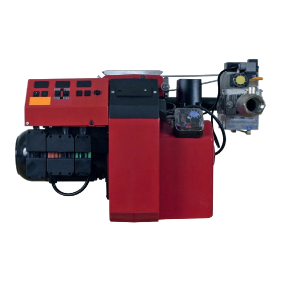
DESCRIPTION 2-Stage Components 1. Flame cone 15. Air pressure switch 2. Connection flange Fuse holder 3. Guide bar 17. Indicating lamp Stage 2 4. Fan wheel 18. Switch I-II 5. Fan house 19. Indicating lamp Stage I 6. Shrouded disc 20. -
Page 7: Modulating
DESCRIPTION Modulating Components 15. Air pressure switch 1. Flame cone 16. Fuse holder 2. Connection flange 17. Change-over switch 3. Guide bar increase-decrease 4. Fan wheel 18. Change-over switch 5. Fan house manually-automatically 6. Shrouded disc 19. Indicating lamp 7. Ignition electrode 20. -
Page 8: Technical Data
TECHNICAL DATA Type designation BG550/BG550LN/BG650 Dimensions 290* 690* Length of Flange Burner tube Burner tube Length of Flange Burner tube Burner tube burner tube Measure B Measure C Measure D burner tube Measure B Measure C Measure D... -
Page 9: Output Range
G25 140-600 17,4 74,4 G30 140-620 19,2 30-50 G31 140-620 25,4 30-50 BG550LN G20 140-620 14,8 35,6 G25 140-620 17,4 76,9 BG650 G20 200-1125 21,2 119,0 G25 200-1125 24,8 139,6 G30 200-1125 34,9 30-50 G31 200-1125 46,0 30-50 Type kWh/m kWh/kg... -
Page 10: Working Field
BG550 BG550 (G25) Measured (test) Capacity kW BG550LN 140-620 kW BG550LN Measured (test) Capacity kW BG650 200-1125 kW BG650 Measured (test) 1000 1100 1200 Unbroken line is the approved Capacity kW working field as per EN 676. 3(3) 172 215 60 05-01... -
Page 11: Skeleton Diagrams
8. Air damper motor 9. Air pressure switch Gas burner control Pos. 5b, 7: Components not required according to EN 676. Required over 1200 kW according to EN 676. When Bio gas is used, Bentone shall always be contacted. 172 415 15 06-01... -
Page 12: Mounting Of The Burner
MOUNTING OF THE BURNER Fit the burner to the boiler by means of 4 bolts M12. For flange and bolt dimensions see technical data. If for some reason you want to separate the burner from the gas flange with burner head and valve package you can do so. Do like this: - Remove the cover of the fan housing. -
Page 13: Electric Equipment
ELECTRIC EQUIPMENT Wiring diagram LGB22/LMG22/LME22 (BG550/BG650) 2-Stage 1(2) 172 435 80 08-01... -
Page 14: List Of Components Lgb22/Lmg22/Lme22 (Bg550/Bg650) 2-Stage
ELECTRIC EQUIPMENT List of components LGB22/LMG22/LME22 (BG550/BG650) 2-Stage A1 Gas burner control S7 Main switch 3-phase B1 Ionization electrode S8 Air pressure switch F1 Operation fuse S20 Main switch 1-phase F2 Operation fuse T1 Ignition transformer H1 Lamp, low capacity... -
Page 15: Wiring Diagram Lmg22/Lme22 (Bg550/Bg550Ln/Bg650) Modulating
ELECTRIC EQUIPMENT Wiring diagram LMG22/LME22 (BG550/BG550LN/BG650) Modulating 1(2) 172 435 43 08-02... -
Page 16: List Of Components Lmg22/Lme22 (Bg550/Bg550Ln/Bg650) Modulating
ELECTRIC EQUIPMENT List of components LMG22/LME22 (BG550/BG550LN/BG650) Modulating A1 Gas burner control S12 Change-over switch, Increase- A2 Power control Reduce A3 Valve, leak tester, S15 Control thermostat, 3-pole Dungs VPS 504 (only for 2-stage sliding) B1 Ionization electrode S20 Main switch 1-phase... -
Page 17: Wiring Diagram Lmg22 (Bg550/Bg550Ln/Bg650) Modulating With R316
ELECTRIC EQUIPMENT Wiring diagram LMG22 (BG550/BG550LN/BG650) Modulating with R316 1(2) 172 435 99 08-01... -
Page 18: List Of Components Lmg22 (Bg550/Bg550Ln/Bg650) Modulating With R316
ELECTRIC EQUIPMENT List of components LMG22 (BG550/BG550LN/BG650) Modulating with R316 Gas burner control S8 Air pressure switch Valve, leak tester, S11 Change-over switch, Aut.-man. Dungs VPS 504 S12 Change-over switch, Increase- Power control R316 Reduce A6(2) PT 100-sensor, S20 Main switch 1-phase... -
Page 19: Control Diagnosis Under Fault Conditions And Lockout Indication
ELECTRIC EQUIPMENT Control diagnosis under fault conditions and lockout indication Gas burner control: LGB ... Lock-out and Control Programme Indication The position of the cam can be read through the sight-glass. Under fault condition the programme is stopped and thus also the lock-out indicator. The symbol visible on the cam indicates both the position in the programme run and the type of fault. -
Page 20: Control Diagnosis Under Fault Conditions And Lockout Indication
ELECTRIC EQUIPMENT Control diagnosis under fault conditions and lockout indication Gas burner control: LMG ... Diagnosis of cause of fault After lockout, the red fault LED is steady on. For reading the cause of fault, refer to the blink code given in the following table: Red LED on Press lockout reset button for >... -
Page 21: Control Program When Disruption; Disruption Display
ELECTRICAL EQUIPMENT Control program when disruption; disruption display Gas burner control: LME..Colour codes Colour code table for multi-coloured signal lamps (Light diodes) Status Colour codes Colours Waiting time «tw», other waiting times Ignition phase, ignition checked Flashing yellow Normal operation Green Operation, poor flame signal Flashing green... - Page 22 ELECTRICAL EQUIPMENT Control program when disruption; disruption display Gas burner control: LME..Alarm control table Red flashing code on Possible causes signal lamp (LED) Flashing 2 x No flame at End of «TSA» •• - Defective or obscured flame monitor - Defective or obscured fuel valves - Poor burner installation - Defective ignition unit...
-
Page 23: Wiring Diagram Lfl1
ELECTRIC EQUIPMENT Wiring diagram LFL1... (BG550/BG650) 2-Stage 1(2) 172 435 78 04-01... -
Page 24: List Of Components Lfl1
ELECTRIC EQUIPMENT List of components LFL1... (BG550/BG650) 2-Stage A1 Gas burner control S6 Control thermostat, stage 2 A3 Valve, leak tester, S7 Main switch 3-phase Dungs VPS 504 S8 Air pressure switch B1 Ionization electrode S10 Gas pressure switch, max... -
Page 25: Wiring Diagram Lfl1
ELECTRIC EQUIPMENT Wiring diagram LFL1... (BG550/BG550LN/BG650) Modulating 1(2) 172 435 77 04-01... -
Page 26: List Of Components Lfl1
ELECTRIC EQUIPMENT List of components LFL1... (BG550/BG550LN/BG650) Modulating A1 Gas burner control S10 Gas pressure switch, max. A2 Power control S11 Change-over switch, Aut.-man. A3 Valve, leak tester, S12 Change-over switch, Increase- Dungs VPS 504 Reduce B1 Ionization electrode S15 Control thermostat, 3-pole... -
Page 27: Wiring Diagram Lfl1
ELECTRIC EQUIPMENT Wiring diagram LFL1... (BG550/BG550LN/BG650) Modulating with R316 1(2) 172 435 94 07-01... -
Page 28: List Of Components Lfl1
ELECTRIC EQUIPMENT List of components LFL1... (BG550/BG550LN/BG650) Modulating with R316 Gas burner control S7 Main switch 3-phase Valve, leak tester, S8 Air pressure switch Dungs VPS 504 S10 Gas pressure switch, max. Power control R316 S11 Change-over switch, Aut.-man. A6(2) PT 100-sensor, Thermocouple,... -
Page 29: Wiring Diagram Lfl1
ELECTRIC EQUIPMENT Wiring diagram LFL1... (BG550/BG650) 2-Stage 1(2) 172 435 83 05-01... -
Page 30: List Of Components Lfl1
ELECTRIC EQUIPMENT List of components LFL1... (BG550/BG650) 2-Stage A1 Gas burner control S6 Control thermostat, stage 2 A3 Valve, leak tester, S7 Main switch 3-phase Dungs VPS 504 S8 Air pressure switch R1 UV-Detector S10 Gas pressure switch, max F1 Operation fuse... -
Page 31: Control Programme Under Fault Conditions And Lockout Indication Lfl1
ELECTRIC EQUIPMENT Control programme under fault conditions and lockout indication LFL1..In the event of fault conditions the fuel supply is always interrupted immedia- tely and, simultaneously, the sequence switch stops and thus the lockout indicator. The symbol appearing above the reading mark indicates the kind of fault: No start, because, e.g., the CLOSE signal has not been supplied to terminal 8 or a... -
Page 32: Measures And Checks Before Start-Up
MEASURES AND CHECKS BEFORE START-UP 2-Stage or modulating burners General rules Care should be taken by the installer to ensure that no electrical cables or fuel/gas pipes are trapped or damaged during installation or service/ maintenance. Inner assembly Ensure that the ignition and ionisation electrodes are correctly adjusted. The sketch (see separate page) shows the correct measurements. -
Page 33: Inner Assembly
MEASURES AND CHECKS BEFORE START-UP Inner assembly Town gas Inner assembly Natural gas, LPG 3-3,5 Inner assembly Biogas ((UV-detector) 10-12 172 155 13 04-01... -
Page 34: Inner Assembly Bg 550Ln
MEASURES AND CHECKS BEFORE START-UP Inner assembly BG 550LN A = 10 mm Front edge Brake plate B = 3 mm A = Position Ionisation detector B = Position Ignition electrode 172 155 14 04-01... -
Page 35: Determination Of Gas Volume For The Installation
DETERMINATION OF GAS VOLUME FOR THE INSTALLATION Specifications on natural gas, town gas and biogas vary. For more exact information please contact the gas distributor. Net calorific value Gas quality kWh/Nm kJ/Nm kcal/Nm Natural gas 10.3 37 144 8 865 Propane 26.0 93 647... -
Page 36: Gas Solenoid Valve Mvd
GAS SOLENOID VALVE MVD MVD: 1-step valve fast opening with max. flow adjustment. 1. Protection cover 2. Flow adjustment 3. Lock nut Flow adjustment MVD/5 Remove protection cover 1. Loosen lock nut 3. Turn the flow adjustment screw 2 to the right = gas flow decrea-ses or to the left = gas flow increases. -
Page 37: Operation And Assembly Instructions
OPERATION AND ASSEMBLY INSTRUCTIONS Double solenoid valve Type DMV-D.../11 Type DMV-DLE.../11 Nominal widths Rp 1/2 - Rp 2 Electrical connection IEC 730-1 (VDE 0631 T1) Volt U n ~(AC) 230 V Valve 2 x Class A Ambient temperature -15 °C … +60 °C Family 1 + 2 + 3 Max. - Page 38 OPERATION AND ASSEMBLY INSTRUCTIONS DMV 525/11 Pressure taps 1, 2, 3, 5 Sealing plug Screw plugs 1,2,3 and 5 may also be replaced by a measuring socket G 1/8 DIN ISO 228. 1. Loosen screws A and B do not remove.
- Page 39 OPERATION AND ASSEMBLY INSTRUCTIONS 7. DMV-DLE ° Rapid stroke adjustment V start Factory setting DMV-DLE: Rapid stroke not adjusted 1. Unscrew the adjustment cap E from the hydraulic brake. 2. Turn the adjustment cap and use as a tool. 3. Turn a-clockwise = increase rapid stroke (+).
-
Page 40: Operation And Assembly Instructions
OPERATION AND ASSEMBLY INSTRUCTIONS Gas pressure regulator Type FRS Nominal diameters Rp 3/8 - Rp 2 1/2 DN 40 - DN 150 Never close vent nozzle! Vent plug 2. Pressure taps Vent nozzle 1. Vent plug 2. Connection for external pulse G 1/4 screw plug ISO 228, on both sides, optional. - Page 41 OPERATION AND ASSEMBLY INSTRUCTIONS Do not use unit as lever. 100 125 150 3/8 1/2 2 1/2 70 105 225 340 610 1100 1600 2400 5000 6000 7600 max. (Nm) _ 10s < 125 200 250 max. (Nm) _ 10s <...
-
Page 42: Multi-Bloc, Mb-Zrdle 405 - 420 B01
MULTI-BLOC, MB-ZRDLE 405 - 420 B01 1. Ball valve 2. Fixing flange 3. Gas pressure switch 4. Governor with pressure adjustment 5. Protective cover, start gas adjustment 6. Hydraulic device, adjustment of stage 2 7. Lock screw for flow adjustment 8. -
Page 43: Flow Adjustment 2-Stage Design
MULTI-BLOC, MB-ZRDLE 405 - 420 B01 Flow adjustment 2-stage design For stage 1, loosen the lock screw a. Turn the hydraulic device e: to the right = the gas flow is reduced to the left = the gas flow is increased For stage 2, turn the hydraulic device b: to the right = the gas flow is reduced Åt vänster = the gas flow is increased... -
Page 44: Multi-Bloc, Mb-Vef 412 - 425 B01
MULTI-BLOC, MB-VEF 412 - 425 B01 View 17 2 16 11 18 1. Electrical connection gas pressure switch mini 2. Electrical connection gas valve 3. Pressure switch mini 4. Flange connection inlet 5. Test point connection 1/8" before V 6. Filter (on Multi-Bloc 425 external filter) 7. -
Page 45: Technical Data
MULTI-BLOC, MB-VEF 412 - 425 B01 Technical data Max inlet pressure 360 mbar Valves V class A group 2 in accordance with EN 161 Governor class A group 2 in accordance with EN88 Ratio V P 0,75:1-3:1 Filter according to DIN 3386 Ambient temperature -15°C- +70°C Protection standard type IP54 (according to IEC 529, DIN 40050) Gas family 1 +2 +3... -
Page 46: Damper Motor 2-Stage
DAMPER MOTOR 2-STAGE Air adjustment The damper motor turns the damper between three pre-set positions: fully closed, low load, full load. These positons are controlled in the motor by cams of different colours. The black cam controls the gas valve for full load. If the air volume needs changing: Remove the cover of the damper motor and change the position of the cams by turning them with the tools accompanying the burner. -
Page 47: Damper Motor Modulating
DAMPER MOTOR MODULATING - Before the burner starts vent the lines to make sure that there is gas vailable at the multibloc - Use an allen key size 2,5 mm for adjusting N and V - Connect a pressure gauge for measur-ing P , (advisable to find out if the valves are open) - Set the switch in position MAN. -
Page 48: General Instructions
GENERAL INSTRUCTIONS Adjustment of burner The burner is from the factory pre-set to an average value that must then be adjusted to the boiler in question. All burner adjustments must be made in accordance with boiler manu-facturers instructions.These must include the checking of flue gas temperatures, average water temperature and or O concentration. -
Page 49: Flame Monitoring And Measurement Of Ionisation Current
GENERAL INSTRUCTION Flame monitoring and measurement of ionisation current The burner is monitored according to the ionisation principle. Check the ionisation current on start-up and on each service call. The reason for a low ionisation current may be leaking currents, bad connection to earth, dirt or a faulty position of the flame electrode in the burner head. -
Page 50: Uv-Detector
GENERAL INSTRUCTION UV-detector This should not be exposed to temperatures exceeding 60°C. The current passing through the UV-detector, when it is being illuminated, should be at least 70 μ A for LFL1.. This current can be measured by means of a moving coil instrument. -
Page 51: Adjustment Of Air Pressure Switch
GENERAL INSTRUCTION Adjustment of air pressure switch The air pressure switch should stop the burner, if the air volume is reduced. The air proving device shall be adjusted in such a way that if there is insufficient air supply at the highest or lowest burner operating stage, the device operates before the supervised pressure is less than 80% of the pressure at the controlled stage and the CO content of the combustion products exceeds 1% by volume. -
Page 52: Leakage Control, Dungs Vps 504 Series 2
LEAKAGE CONTROL, DUNGS VPS 504 SERIES 2 Technical data ≤ 4,0 l Test volume ≈ 20 mbar Pressure increase using motor pumps Backup (customer supply) 10A fast or 6.3A slow Fuse integrated in housing, replaceable T6,3L 250V (IEC 127-2/111) (DIN41662) Switching capacity Operating outputs SO1, SO2,SO4: 4A Faul output T7: 1A... -
Page 53: Program Sequence Schedule
Differential pressure sensor Release signal Electrical connection VPS 504 Series 02 The VPS 504 is connected in series between the temperature regulator and the control box via a 7-pole plug connector. See the Bentone wiring diagram. tight untight Lock-out Operation... -
Page 54: Handing Over Of The Installation
HANDING OVER OF THE INSTALLATION - Make repeated start attempts to ensure that the adjustments function. - Close the ball valve during operation to check that the gas switch switches off at the set value. - Remove the hose for the air pressure switch to check that the burner locks out. -
Page 55: Declaration Of Conformity
BG 100, BG 150, BG 200, STG 120, STG 146, BG 300,BG 300LN, BG 400, BG 400LN BG 450,BG 450LN, ......................................BG 500,BG 500LN, BG550, BG550LN, BG 600,BG 600LN, BG650, BG 700,BG 700LN, BG 800,BG 800LN ........................................and BG950 all fan gas burners .......................................... -
Page 56: Fault Location Guide
FAULT LOCATION GUIDE Gas burner The basis for a trouble free operation can only be ensured by the correct combined effect of the three factors: electricity, gas flow and combustion air. Should any of these factors change, troubles may arise. It has been proved that many troubles have rather simple causes. - Page 57 Cause Remedy No flame establishment despite a trouble free start The gas solenoid valve defective Replace The gas solenoid valve does not open despite Replace coil or the whole valve if necessary. its obtaining voltage No voltage to the solenoid valve Check the contact No electrical connection through Test the adjustment and the function of the air pres-...
- Page 58 Cause Remedy Pulsations at start The ignition electrodes are wrongly adjusted Re-adjust. The gas pressure is too high Check and adjust by means of a pressure gauge and a pressure adjustment valve. The flue gas side is blocked Check the chimney flue. Pulsations during operation The burner is not correctly adjusted Re-adjust...
Need help?
Do you have a question about the BG650 and is the answer not in the manual?
Questions and answers