
Subscribe to Our Youtube Channel
Related Manuals for Bentone BG 450 M J IP20


Summary of Contents for Bentone BG 450 M J IP20
- Page 1 CR00264 178 125 76-3 2021-06-21 Providing sustainable energy solutions worldwide Installation- and maintenance instruction BG 450 M J/K IP20 LME22.233C2 MB-VEF 412 Translation of the original instructions.
- Page 2 1~230V 1,0A 50Hz IP 20 Motor supply MADE IN SWEDEN BY 1. Manualer på övriga språk 1. Manuals in other languages 1. Manualer på andre sprog 2. www.bentone.com\ 2. www.bentone.com\download 2. www.bentone.com\download nedladdning or scan QR-code. eller scan QR-koden. eller scanna QR-koden.
-
Page 3: Table Of Contents
5. Setting the burner ___________________________________ 19 5.1 Setting the combustion assembly ___________________ 19 5.2 Setting the air pressure switch _____________________ 20 5.3 Setting the min. gas pressure switch ________________ 21 5.4 Setting the power monitor _________________________ 22 5.5 Skeleton diagrams _______________________________ 23 Bentone... -
Page 4: General Information
• Burner pipes, fan wheels and air dampers may contain sharp edges. • The surface temperature of the burner’s components can exceed 60 °C. • Caution: The burner has moving parts, and there is risk of crushing injuries. 172 515 01 2018-01-02 Bentone... - Page 5 Open windows and doors. Close the gas ball valve. Warn residents; do not use doorbells. Evacuate the building. Notify the installer or gas supplier once the building has been evacuated. Bentone...
- Page 6 Delivery check • Make sure everything is delivered and the goods have not been damaged during transit. • If something is wrong with a delivery, report it to the supplier. • Transport damage must be reported to the shipping company. Bentone...
-
Page 7: Technical Data
* The above dimensions are max. measurements. Depending on the components used, the measurements may vary. ** Min. recommended distance to fl oor. 2.1.1 Heat generator connection dimensions (Ø 210) Ø 255-290 Ø 170 BG 450 172 525 69-1 2021-05-10 Bentone... -
Page 8: Capacity Range
8126 Natural gas 29.25 6986 Butane 32.5 116.09 27728 Propane 24.6 88.00 21019 Biogas 21,60 5159 Gas quantity and capacity vary according to grade of gas and connection pressure. 2.3 Appliance categories Only dry gas is permitted for use. Bentone... -
Page 9: Working Field
Alt.2 The burner’s noise level can be reduced by connecting the burner’s air intake to the air duct that opens into an appropriate location. Installation must be done so it does not prevent air supply to the burner. Bentone... -
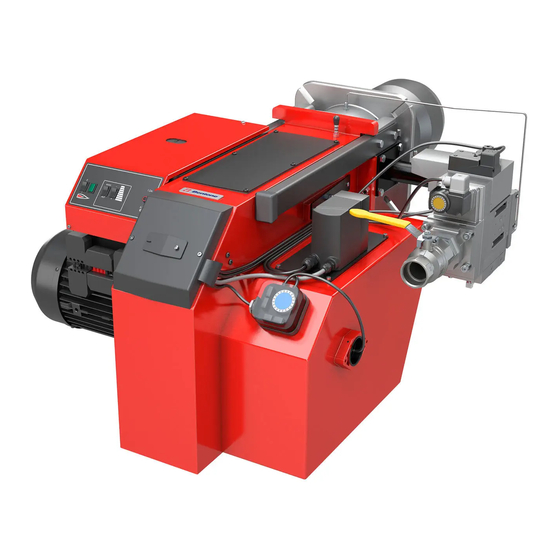
Page 10: Description
Air intake Switch 0-1 Electrical panel Air damper Damper motor Max. gas pressure switch Air pressure switch Relay box Fan housing Impulse pipe Electrical connection Brake plate Gas pressure switch MultiBloc Ignition electrode Changeover switch, increase- decrease Ionisation electrode Bentone... -
Page 11: General Instructions
Adjust the burner to appr. 20% excess air in accordance with the table. Check the flue gas temperature. Calculate the efficiency. Check also the actual gas volume on the gas meter so that the correct input is achieved. 172 515 03-2 Bentone... -
Page 12: Installation
(see Basic settings). Note that it is only a basic setting which should be adjusted once the burner has been started. If an electric connection other than the one recommended by Enertech is used, a risk of damage and injury can arise. 172 515 03-2 Bentone... -
Page 13: Handling And Lifting Instruction
4.6 Handling and lifting instruction 4.6.1 BG 450 The lifting aids we use here are available as accessory. 172 515 29 2018-01-02 Bentone... -
Page 14: Mounting On The Boiler
Once the gas flange is fitted to the boiler, it is easy to lift the burner body up onto the guides. Assemble the burner in reverse order to its disassembly. Check the gas tightness. Service position 172 515 30 2018-01-15 Bentone... -
Page 15: Inspection Of Gas Nozzle Before Commissioning
Re-assemble the burner in reverse order to that described above. When re- assembling, make sure that the O-ring located between the gas nozzle and the gas flange is in the correct position when the nozzle is re-fitted. Service position 172 515 31 2018-01-15 Bentone... -
Page 16: Leakage Control
The gas valve is energized and opens and flame is established. At the end of the safety time (2-3 sec.) the gas control locks out. The solenoid valve and the motor will be ”dead”. Remove the link from the gas pressure switch after the test is finished. Bentone... -
Page 17: Gas Nozzle
4.10 Gas nozzle Natural gas Propan Biogas (UV detector) Bentone... -
Page 18: Setting Damper Motor, Modulating Operation
The function is used when switch in position MIN and (if mounted) gas servicing air dampers. pressure switch max in position MAX. Solenoid valve High load (black) High load (red) Low load (orange) Closed air damper (blue) Release button 172 515 15-2 2021-05-03 Bentone... -
Page 19: Setting The Burner
A left turn opens the brake plate, providing a lower pressure drop and more air to the combustion process. A right turn closes the brake plate, providing a higher pressure drop and less air to the combustion process. 172 515 32 2018-01-15 Bentone... -
Page 20: Setting The Air Pressure Switch
This is to ensure the reliable function of the burner. If breakdowns or interruptions occur, the air pressure switch is probably set to a too narrow position. Fit the protective cover, screw (Y). Bentone... -
Page 21: Setting The Min. Gas Pressure Switch
The tolerance on the scale for the min. gas pressure switch is approx. ±15%. Open the ball valve. Remove the pressure gauge and close the pressure outlet (X). Check the gas tightness. Fit the protective cover, screw (Y). Bentone... -
Page 22: Setting The Power Monitor
Test run the burner in the set power range. Remove the pressure gauge and close the test socket. Fit the cover on the power monitor and tighten the screw (Y). Check the gas tightness. Setting range: 2.5–50 mbar ÜB 5-150 mbar ÜB 172 525 70-1 2021-05-10 Bentone... -
Page 23: Skeleton Diagrams
Safety valve Valve proving system Air pressure switch Gas burner control Pos. 5b, 7: Components not required according to EN 676. Required over 1200 kW according to EN 676.hhh 172 515 05 2018-01-02 Bentone... -
Page 24: Multibloc Mb-Vef 407-412
It is possible to connect a leakage control VPS 504 and a gas pressure switch maxi. ) NB. The impulse line P can be replaced by an impulse fl ange on the multibloc. The impulse line P is then placed inside this fl ange. 172 515 16 2018-01-03 Bentone... - Page 25 ∆ P 6.5.4 Adjustment possibilities Effective burner pressure ∆ P ∆P Effective fan pressure max. = 100 mbar ∆ P ∆ P MB-VEF Adjustment range Adjustment range N=+2 ∆pBr, min =0,5 mbar ∆P N=-2 , max. = 100 mbar Bentone...
- Page 26 6.5.5 Pressure taps min. 5 x DN p , extern PN1, DN 4 1,3,4,5 G 1/8 screwed sealing plug 2 Measuring nozzle 6,7,8 G 1/8 female thread for pL ,pF ,pBr pulse lines 6.5.6 Electrical connection S 10/S 30 Bentone...
-
Page 27: Recommended Excess Air When Using Default Setting
Lower heat value Hu at normal state 15°C and 1013.25 mbar EN676 Grade of gas kWh/Nm MJ/Nm kcal/Nm Natural gas 34.02 8126 Natural gas 29.25 6986 Butane 32.5 116.09 27728 Propane 24.6 88.00 21019 Biogas 21,60 5159 172 515 13 Bentone... - Page 28 Temperature of gas at the gas meter [°C] Barometer reading [mbar] Pressure of gas at the gas meter [mbar] Factor calculated for multiplication with flow in Nm /h to arrive at actual flow in Nm Actual flow · 273+T 1013.25 Bentone...
-
Page 29: Calculating The Quantity Of Gas Supplied
= Time for a certain quantity of gas consumed by the burner. M = Quantity of gas consumed. V = Actual gas flow Calculation example: t = 1 min 10 s M = 330 dm (litre) 0.33 m 1000 0.0194 h 3600 0,33 ≈ 17 m 0.0194 Bentone... -
Page 30: Service
Check the ionisation electrode (see chapter Gas nozzle). Replace if necessary. Fit the combustion assembly in reverse order. Press the burner together and lock using the nuts (B). Fit the Euro plugs and turn on the main power supply. Check/adjust the combustion. 172 615 16 2018-01-15 Bentone... -
Page 31: Servicing Air Dampers
Re-install the damper motor and mounting plate on the air intake. Ensure that the damper shaft and control arm are connected correctly. Install the intake grille for the air intake. Press the burner together and lock using the nuts (B). Check/adjust the combustion. Bentone... -
Page 32: Replacement Of Damper Motor, Air
Re-install the damper motor and mounting plate on the air intake. exchange of damper motor. Ensure that the damper shaft and control arm are connected correctly. Connect the damper motor cable. Fit the Euro plugs and turn on the mains power. Check/adjust the combustion. Bentone... -
Page 33: Vibration
Maximum vibration level are 5,0 mm/s • Check all bolts and nuts for correct torque • Check fan wheel for damage and contamination. Change when dirty/ unbalanced • Check motor bearings. If worn change motor/bearings Use lid screw for sensor mounting Bentone... -
Page 34: Flame Monitoring And Ionisation Current Check
Required current to ensure detection Min. DC 3 µA Possible detection current Max. DC 20 µA Operational indicator lamp flashes green <5 µA DC Operational indicator lamp shines green >5 µA DC 7.5.1 Flame monitoring ionisation 172 615 02-2 Bentone... - Page 35 Max. current for flame detection Max. DC 5.5 µA Required current to ensure detection Min. DC 40 µA Possible detection current Max. DC 60 µA Operational indicator lamp flashes green <45 µA DC Operational indicator lamp shines green >45 µA DC Bentone...
-
Page 36: Handing Over Of The Installation
• Is the circulation pump in operation? • Is there a supply of fresh air to the installation? • If integral components are of a different make from what is stated in this manual, see the enclosed loose-leaf. 172 615 04 Bentone... -
Page 37: Electric Equipment
• Installation will block burner operation and a manual restart will be required. Installation must be carried out pursuant to applicable regulations. 172 615 83-1 2021-05-10 Bentone... -
Page 38: Wiring Diagram Lme
10.2 Wiring diagram LME Bentone... -
Page 39: Function Lme
The operation of the burner can now be stopped with the control switch or thermostat If the gas burner control is blocked Red light in the gas burner control is lit. The burner is restarted by pushing the reset button Bentone... -
Page 40: Control Program At Faults; Fault Mode Indicator Lme
(waiting period ≥ 10 s) 10.4.1.2 Limiting of starting repetitions LME 11... has a function with start repetition if the flame is not created at start or disappears during operation.. LME 11... allows max. three repetitions during continuous starting cycle. Bentone... - Page 41 3 s. To go back Q1 = AGQ 3... to the normal position, press and hold the reset button longer than 3 s. If the gas burner control is in the alarm position, it is reset by pressing the reset button 0.5...3 s. Bentone...
-
Page 42: Troubleshooting
Burner control faulty Replace Air pressure gauge incorrectly set or faulty Check the settings and reset, or replace No acknowledgement signal due to incorrect adjustment or Check the settings and realign. misalignment of the control motor cams. 172 615 06 2018-01-10 Bentone... - Page 43 Poor draught conditions. Check the chimney. Flue gas temperature too high. Boiler overloaded Decrease the gas volume, sweep the chimney if necessary. content too low. Choke the air supply. Check the boiler for any leakages. Choke the draught if too high. Bentone...
- Page 44 Flame at incorrect angle due to combustion head out of position. Check the combustion head and readjust. Condensation build up in boiler and chimney: Flue gas temperature too low or gas volume too low. Raise the flue gas temperature by increasing gas volume Insulate the chimney. Bentone...
-
Page 45: General Instructions For Gasburners
12. General instructions for gasburners 12.4.1 Installation Follow standards and instructions applicable to the Check that the burner is adapted to the gas quality in installation of gas burners. question. Ensure that the electric installation is made in accordance Check that the input pressure of the gas is correct. with existing regulations. - Page 46 Service- and inspection card Installation Boiler Name: Type: Efficiency kW: Address: Burner Type: Efficiency kW: Installed by: Date: Date gas/h Governor Fluegas Ionisation Pressure Efficiency temp current Fire Chimney room Measu- rement Before After °C µ A mbar mbar Small Flame Large Flame...
- Page 52 Enertech AB. P.O Box 309, SE-341 26 Ljungby. www.bentone.com...
Need help?
Do you have a question about the BG 450 M J IP20 and is the answer not in the manual?
Questions and answers