
Related Manuals for Krone EASYCOLLECT 9000


Summary of Contents for Krone EASYCOLLECT 9000
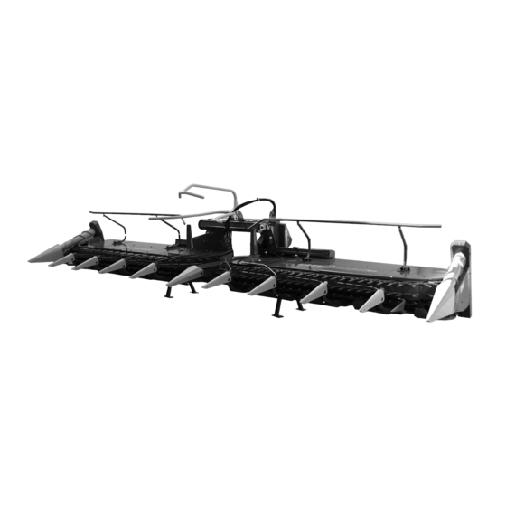
- Page 1 Operating instructions 150 000 054 00 EN Maize header EASYCOLLECT 6000 EASYCOLLECT 7500 EASYCOLLECT 9000 (Machine No. 535 500 or higher)
- Page 2 (Dr.-Ing. Josef Horstmann, Managing Director) (Wolfgang Ungruh, Head of Quality Assurance) Dear Customer: These are the operating instructions for the KRONE product that you have purchased. These operating instructions contain important information for the correct use and safe operation of the machine.
-
Page 3: Table Of Contents
Contents Contents General aspects ................I -1 Intended use ......................I -1 Technical data ......................I -1 1.2.1 General aspects ...................... I -1 1.2.2 Address of the manufacturer ..................I -1 1.2.3 Declaration ......................I -1 1.2.4 Designation ......................I -1 1.2.5 Information for enquiries and orders ................ - Page 4 Lubrication chart ....................IV -16 4.13 Storing when not in use ..................IV -17 Commissioning ................. A -1 A1.1 Fitting the additional weights ................... A -1 A1.2 Fitting the discharge extension (only for EasyCollect 7500; EasyCollect 9000) ..A -2...
-
Page 5: General Aspects
1.1 Intended use The Krone EASYCOLLECT 6000, EASYCOLLECT 7500 and EASYCOLLECT 9000 maize header is a harvesting attachment with adapter frame for attachment to forage harvesters and is used for harvesting maize and other forage crop with stalks independently of the rows. -
Page 6: Intended Use
General aspects 1.2.6 Intended use The Krone EASYCOLLECT 6000, EASYCOLLECT 7500 and EASYCOLLECT 9000 may be attached only to carrier vehicles for which the relevant adapter frame is released (observe operating permission of the carrier vehicle). It is built exclusively for customary use in agricultural work (use as intended), see also Section 1.1 Intended... - Page 7 General aspects 1.2.8 Additional weights on the BigX To ensure safe and reliable operation of the self- propelled forage harvester with the maize header attached, especially in road traffic, additional weights (Z) must be connected to the rear frame. Steel design EC100665 Item Designation of...
- Page 8 General aspects I - 4...
-
Page 9: Safety
Safety 2.2 Safety instructions and Safety accident prevention 2.1 Identifying important regulations information in the operating 2.2.1 Personnel qualification and training instructions The maize header may be used, maintained and Important safety instructions in the present operating repaired only by persons who are familiar with it and instructions are identified with the general hazard have been instructed about the dangers connected with symbol. -
Page 10: Safety And Accident Prevention Regulations
Safety Compliance with the relevant legal regulations is 15. Operating devices (ropes, chains, rods, etc.) of mandatory in traffic on public roads (in the Federal remotely operated devices must be run so that they Republic of Germany, for example, the StVZO (Road do not trigger unintended movements in all Traffic Type Approval Law and the StVO (Road Traffic transport and working positions. -
Page 11: Attached Devices
Safety 2.2.5 Attached devices 9. Before switching on the PTO shaft make sure that no person is in the hazard area of the device! 1. Special care is required when coupling and 10. Never switch on the PTO with the engine turned off! uncoupling the maize header onto or from the forage harvester! 11. -
Page 12: Maintenance
When performing electric welding work on the forage harvester and mounted implements, disconnect cables at the generator and battery! 9. Spare parts must at least correspond to the technical requirements defined by the device manufacturer! This is guaranteed by original KRONE spare parts! II - 4... -
Page 13: Safety Instructions On The Machine
Safety 2.3 Safety instructions on the machine The KRONE maize header is equipped with all necessary safety devices (protective devices). Not all dangerous places on this machine can be completely secured in reference to maintaining the functionality of the machine. -
Page 14: Location Of The Warning Pictograms On The Machine
Safety Spænd fastgørelsesskruerne 2.3.1 Location of the warning pictograms on the machine. EC200021 Before commissioning the Do not touch any moving machine, read the parts of the machine. operating instructions and Wait until they have come safety instructions and to a complete stop. heed them. - Page 15 Safety Never reach into the area where there is danger of Danger due to revolving crushing as long as parts worm auger. may be in motion there. Order No. 939 520-1 (2x) Order No. 942 196-1 (2x) Do not climb onto the machine if the PTO shaft is Do not stay in the swivel connected and the engine...
-
Page 16: Location Of The General Warning Signs On The Machine
2.3.2 Location of the general warning signs on the machine EC200022 EASYCOLLECT 6000 Order No. 942 301-0 EASYCOLLECT 6000 Order No. 942 437-0 EASYCOLLECT 7500/9000 Order No. 942 341-1 EASYCOLLECT 7500 Order No. 942 414-0 EASYCOLLECT 9000 Order No. 942 415-0 II - 8... - Page 17 Order No. 942 437-0 Order No. 942 301-0 (7500/6000) EASYCOLLECT 7500 Order No. 942 438-0 Order No. 942 320-0 (9000) (2x) EASYCOLLECT 9000 Order No. 942 439-0 (2x) Fully reflecting adhesive strips Order No. 924 625-0 Order No. 942 440-0 (2x) Order No.
- Page 18 Safety II - 10...
-
Page 19: Start-Up
4 m is not exceeded. Do not open or remove the protective The EASYCOLLECT 9000 maize equipment when the engine is header must be placed on a special running transport carriage for road transport. -
Page 20: Attaching
Start-up 3.4 Attaching 3.4.1 Adjusting the adapter frame Only when the forage harvester is initially attached or replaced. • Measure the axle base „a“ between holding claw (1) and locking hook (2) on the pendulum frame of the forage harvester. EC200080 •... -
Page 21: Pendulum Frame
Start-up 3.4.2 Pendulum frame • Lower the pendulum frame (1) of the forage harvester all the way. • Align the pendulum frame (1) of the forage harvester horizontally. • Locking hooks (2) must be opened. If necessary, open them with the locking lever (3). •... - Page 22 Start-up • Swing the locking lever (2) to the rear and engage it on the locking pin (3) with spring plug (4). Check that the pendulum frame hooks correctly into the holding bolts (1) and the locking hooks on both sides. •...
-
Page 23: Transport Position
Start-up 3.5 Transport position Before folding the maize header into its transporting position, turn off the drive. The maize header may be folded in only with complete standstill of the drive. 3.5.1 Folding in the tubular bar on the right/left Transport must only be performed with the right/left tubular bars folded inward. -
Page 24: Swinging The Maize Header Up
Start-up 3.5.2 Swinging the maize header up • Swing the maize header (1) up completely with the forage harvester hydraulics until the latch (2) snaps into place. • Check that the outriggers are locked on both sides in the latches (2). EC200200 III - 6... -
Page 25: Parking Supports In Transport Position On The Right/Left
Start-up 3.5.3 Parking supports in transport position on the right/left • Stop the machine. • Remove the spring cotter pins (2) and push in parking supports (1) . • Secure position with spring cotter pin (2). EC200220 3.5.4 Installing guard on the right/left •... -
Page 26: Installing The Front Guard
Start-up 3.5.6 Installing the front guard • Fit the front guard (1) on the right and left onto the holder on the support and centrally on the central tip, pay attention to the prescribed position of the warning stripes (2) (the hatching must point downwards and outwards). -
Page 27: Folding Up The Tubular Bar On The Right/Left
Start-up 3.6.3 Folding up the tubular bar on the right/left • Swing the maize header into the working position with the forage harvester hydraulics. • Stop the machine. • Pull off the linch pins (2) on both holders and fold the tubular arm (1) up to the outside. -
Page 28: Using The Machine For Work
Start-up 3.7 Using the machine for work 3.7.1 Special safety instructions Keep persons out of the hazardous Work on the maize header must only area. If persons do approach the be performed when the engine is hazardous area, please turn off the stopped and turned off and the machine immediately. -
Page 29: Autopilot (Optional)
Start-up 3.7.4 Autopilot (optional) The autopilot function is available only if sensors (1) and autopilot equipment have been fitted. The automatic pilot guides the forage harvester along the maize row with the sensors on the maize header. EC100630 3.8 Detaching Set the maize header down only on solid and level ground and only with the parking supports extended. - Page 30 Start-up The system should be without pressure on both sides when disconnecting the hydraulic hoses (1). • Disconnect the hydraulic lines (1) at the hydraulic couplings and close off with dust caps. • Pull off the lighting cable (2). • Loosen the connection cable (3) of the sensors.
-
Page 31: Maintenance
Maintenance Maintenance 4.1 Special safety instructions Repair, maintenance and cleaning Only perform tasks on the hydraulic tasks must only be performed while the system when all excess pressure has engine is stopped! been released. Remove the ignition key and secure the Liquid escaping under high pressure forage harvester from being placed in can penetrate through the skin and... -
Page 32: Tightening Torques On The Aluminium Gears
Maintenance 4.2.1 Tightening torques on the 72 Nm aluminium gears 49 Nm 9 Nm 210 Nm 17 Nm 210 Nm EC100660 72 Nm 80 Nm 72 Nm EC100661 49 Nm 85 Nm 72 Nm EC100662 49 Nm 17 Nm 9 Nm 72 Nm 30 Nm 72 Nm... -
Page 33: Gearboxes
Maintenance 4.3 Gearboxes • If no other instructions are given, change the oil once a year on all gears. • Check the oil level before the beginning of the season. • Check all gears daily for any leaks and check the oil level if necessary. -
Page 34: Checking The Oil Level And Changing The Oil In The Transfer Gearbox (Right/Left
Maintenance 4.3.3 Checking the oil level and changing the oil in the transfer gearbox (right/ left) Perform oil level checks and oil change while the maize header is in its working position! Checking the oil level • Unscrew the oil level control screw (2) on the transfer gearbox (1). -
Page 35: Checking The Oil Level And Changing The Oil In The Angular Gearbox (Right/Left
Maintenance Changing the oil • Swing the maize header into its working position. • Unscrew the oil level control screw (2) on the collector gearbox (1) . Collect the oil in a suitable container. • Screw in the oil level control screw (2) again. •... -
Page 36: Checking The Oil Level And Changing The Oil In The Dresser Gearbox (Right/Left
Maintenance 4.3.6 Checking the oil level and changing the oil in the dresser gearbox (right/ left) Check the oil level in the horizontal position of the maize header in transport position! Checking the oil level • Unscrew the oil level control screw (2) on the dresser gearbox (1). -
Page 37: Laid Maize Worm Drive Belt (Right / Left
Maintenance 4.4 Laid maize worm drive belt (right / left) 4.4.1 Checking the drive belt tension Check the drive belt tension after the first 10 operating hours, then every 60 operating hours. • Unscrew the hexagon head screws (2) and remove the protective plate (1). -
Page 38: Collector Pre-Tension (Right / Left
Maintenance 4.5 Collector pre-tension (right / left) 4.5.1 Checking the collector pre-tension Check the collector pre-tension after the first 10 operating hours, then every 60 operating hours. • The compression spring (1) is correctly pre- tensioned if the dimension is “a = 325 - 330” mm. If necessary correct the collector pre-tension. -
Page 39: Scraper (Right / Left
Maintenance 4.6 Scraper (right / left) The distance between the back of the collector (2) and the scraper (1) must not exceed the dimension «a = 3 mm». 4.6.1 Adjusting the scraper • Loosen the screws (3) a little and press the scraper (1) against the back of the collector (2). -
Page 40: Tips
Maintenance 4.7 Tips The lower edges of the side tips (1 right/ 1 left) should be at the same height as the lower edges of the tips (2). The lower edges of the central tip (3) should be about x = 30-50 mm lower than the lower edges of the other tips (a = freely selectable distance to the ground). -
Page 41: Removing The Upper Insert Finger
Maintenance 4.8 Removing the upper insert finger • Removing the upper insert finger EC200465 4.9 Installing PTO shafts Take care in the installation of the PTO shafts (1) that the cross joints (2) are fitted parallel to one another. EC200025 4.10 Hydraulic hose lines Hydraulic hose lines may be used for 6 years at the most after manufacture. -
Page 42: Changing Blades
Maintenance 4.11 Changing blades Wear protective gloves when working on the blades! Check the blades each time before using them and each time after driving for obstacles. Worn, damaged or deformed blades must be replaced immediately. 4.11.1 Changing bow and step blades When replacing observe the left/right cutting direction! •... -
Page 43: Changing Cutting Blades
Maintenance 4.11.2 Changing cutting blades When replacing observe the cutting direction right/left and the number of blades 1 or 2! • To remove the cutting blades (1) (only possible outside in the area of the bow) unscrew the internal hexagon head screw (2). •... -
Page 44: Changing Scraper Blades (Right / Left
Maintenance 4.11.4 Changing scraper blades (right / left) • Unscrew the 2 hexagon head screws (2) and remove the scraper blade (1). • Installation of the new scraper blade (1) in the reverse order of removal, take care that the cutting edge lies against the collector. -
Page 45: Lubrication
Maintenance 4.12 Lubrication 4.12.1 PTO shafts • All PTO shafts have to be lubricated after 250 operating hours in keeping with the data in the operating instructions of the manufacturer of the PTO shaft. 25 h 100 h 250 h EC200024 IV - 15... -
Page 46: Lubrication Chart
Maintenance 4.12.2 Lubrication chart • The lubricating points mentioned below must be lubricated after the operating hours indicated. 25 h 250 h 250 h 25 h 25 h 250 h 250 h optional 25 h EC200023 IV - 16... -
Page 47: Storing When Not In Use
• List all required spare parts and order them in good time. It is easier for your KRONE dealer to provide and install the required parts outside the season. Then the machine will be completely ready for use the coming season. - Page 48 Maintenance IV - 18...
-
Page 49: A1 Commissioning
Anhang A1 Commissioning • Repair, maintenance and cleaning tasks must only be performed while the engine is stopped! Remove the ignition key and secure the forage harvester from being placed in operation or rolling away unintentionally. • After completing maintenance work reattach all protective devices properly. Avoid skin contact with oil and grease. -
Page 50: A1.2 Fitting The Discharge Extension (Only For Easycollect 7500; Easycollect 9000
Anhang EC100673 A1.2Fitting the discharge extension (only for EasyCollect 7500; EasyCollect 9000) EC100675 EC100674 EC100676 EC100677 I - 2... - Page 51 Anhang I - 3...
- Page 52 . . konsequent, kompetent Maschinenfabrik Bernard Krone GmbH Heinrich-Krone-Straße 10, D-48480 Spelle Postfach 11 63, D-48478 Spelle Phone +049 (0) 59 77/935-0 +049 (0) 59 77/935-339 Internet: http://www.krone.de eMail: info.ldm@krone.de...
Need help?
Do you have a question about the EASYCOLLECT 9000 and is the answer not in the manual?
Questions and answers