Table of Contents
Advertisement
Available languages
Available languages
Quick Links
Advertisement
Chapters
Table of Contents

Related Manuals for Stahl 9411/24 Series


Summary of Contents for Stahl 9411/24 Series
- Page 1 Betriebsanleitung Operating instructions Additional languages www.r-stahl.com DE EN Feldgeräte-Koppler 8 Spurs Zone 2 Ex i Zone 2 Ex i Field Device Coupler 8 Spurs Reihe 9411/24 Series 9411/24...
- Page 3 Betriebsanleitung Additional languages www.r-stahl.com Feldgeräte-Koppler 8 Spurs Zone 2 Ex i Reihe 9411/24...
-
Page 4: Table Of Contents
Inhaltsverzeichnis Allgemeine Angaben ...................3 Hersteller ......................3 Angaben zur Betriebsanleitung ................3 Weitere Dokumente ....................3 Konformität zu Normen und Bestimmungen ............3 Erläuterung der Symbole ..................4 Symbole in der Betriebsanleitung ...............4 Warnhinweise .....................4 Symbole am Gerät ....................5 Sicherheitshinweise ....................5 Aufbewahrung der Betriebsanleitung ..............5 Qualifikation des Personals ................5 Sichere Verwendung ...................5 Umbauten und Änderungen ................6... -
Page 5: De De
• PROFIBUS Montage / Cabling and Assembly, Version: 1.14, Order No.: 8.021 / 8.022, Language: German / English • Fieldbus FoundationTM "System Engineering Guidelines" AG 181,V3.2.1, 2010 Dokumente in weiteren Sprachen, siehe www.r-stahl.com. Konformität zu Normen und Bestimmungen Zertifikate und EU-Konformitätserklärung, siehe www.r-stahl.com. -
Page 6: Erläuterung Der Symbole
Erläuterung der Symbole Erläuterung der Symbole Symbole in der Betriebsanleitung Symbol Bedeutung Tipps und Empfehlungen zum Gebrauch des Geräts Gefahr durch explosionsfähige Atmosphäre Warnhinweise Warnhinweise unbedingt befolgen, um das konstruktive und durch den Betrieb bedingte Risiko zu minimieren. Die Warnhinweise sind wie folgt aufgebaut: •... -
Page 7: Symbole Am Gerät
Normen und Bestimmungen umfasst. Für Tätigkeiten in explosionsgefährdeten Bereichen sind weitere Kenntnisse erforderlich! R. STAHL empfiehlt einen Kenntnisstand, der in folgenden Normen beschrieben wird: • IEC/EN 60079-14 (Projektierung, Auswahl und Errichtung elektrischer Anlagen) • IEC/EN 60079-17 (Prüfung und Instandhaltung elektrischer Anlagen) •... -
Page 8: Umbauten Und Änderungen
Funktion und Geräteaufbau Bei Montage und Installation • Montage und Installation nur durch qualifizierte und autorisierte Personen (siehe Abschnitt "Qualifikation des Personals") durchführen lassen. • Gerät nur in Zonen installieren, für die es aufgrund seiner Kennzeichnung geeignet ist. • Bei Installation und im Betrieb die Angaben (Kennwerte und Bemessungsbetriebs- bedingungen) auf Typ- und Datenschildern sowie die Hinweisschilder am Gerät beachten. -
Page 9: Funktion
Funktion und Geräteaufbau Funktion Einsatzbereich Die Feldgeräte-Koppler dienen zum Anschluss von bis zu acht eigensicheren Feldgeräten an einen nicht-eigensicheren Trunk. Dabei werden Trunk und Spurs galvanisch getrennt. Wird der Koppler im Ex-Bereich eingesetzt, ist er in ein für diesen Bereich zugelassenes Gehäuse einzubauen. - Page 10 Funktion und Geräteaufbau Arbeitsweise Die Feldgeräte können jeweils mit einem Strom von maximal 40 mA versorgt werden. In der Summe sind max. 160 mA für den Nennbetrieb verfügbar. Dieser Strom ist auf die angeschlossenen Feldgeräte aufteilbar z.B.: • 4 x 40 mA •...
-
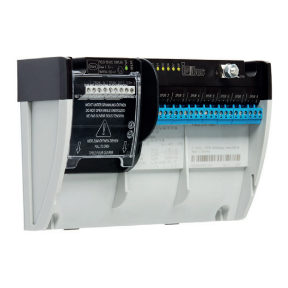
Page 11: Geräteaufbau
Funktion und Geräteaufbau Geräteaufbau 06580E00 Gerätelement Beschreibung Anschlussklemmen Ex nA Bereich Durch aufklappbare Abdeckung (IP30) geschützte Ex nA Anschlussklemmen für Trunk und für Brücke zur Aktivierung des Abschlusswiderstands (Arbeiten an Ex nA Anschlüssen unter Spannung ist in Zone 2 nicht zulässig!) LEDs Betriebsanzeige-LED "PWR"... -
Page 12: Technische Daten
Technische Daten Technische Daten Explosionsschutz Global (IECEx) Gas und Staub IECEx BVS 08.0057X Ex nA [ia Ga] IIC T4 Gc [Ex ia Da] IIIC Europa (ATEX) Gas und Staub BVS 06 ATEX E 004 X E II 3 (1) G Ex nA [ia Ga] IIC T4 Gc E II (1) D [Ex ia Da] IIIC Bescheinigungen und Zertifikate Bescheinigungen... - Page 13 Technische Daten Technische Daten Elektrische Daten Hilfsenergie nicht erforderlich, der Feldgeräte-Koppler wird aus dem Trunk gespeist Galvanische Trennung Ex i Spurs zu 1,5 kV AC Trunk Ex i Spur zu keine galvanische Trennung Ex i Spur Datenübertragung zwischen Trunk passiv, keine Repeaterfunktion und Spurs Max.
- Page 14 Max. kontinuier- 20 mA licher DC Ausgangsstrom alle Spurs Min. Ausgangs- 10 V bei 41 mA spannung Hinweis zur korrekten Projektierung ist das R. STAHL Tool "Fieldbus Wizard" zu verwenden (www.r-stahl.com). Min. 12 V Leerlaufspannung Max. 65 Ω Innenwiderstand Max.
- Page 15 Technische Daten Technische Daten Umgebungsbedingungen Umgebungs- Koppler montiert auf DIN-Schienen: -40 ... +75 °C temperatur Lagertemperatur -40 ... +75 °C Relative Feuchte < 95 % (keine Betauung) Mechanische Daten Anschluss Anschluss- 3-polig Schraub- abziehbare klemmen (+, -, Schirm) klemmen Schraubklemmen Trunk nur für Spurs Ex i Spurs Ex i...
-
Page 16: Projektierung
FISCO nicht Ex i Ex i Power-Management 06799E01 Weitere technische Daten, siehe www.r-stahl.com. Projektierung HINWEIS Ausfall der installierten Geräte im Schaltschrank durch zu hohe Umgebungstemperatur! Nichtbeachten kann zu Sachschäden führen. • Schaltschrank so aufbauen und einrichten, dass er immer innerhalb des zulässigen Temperaturbereichs betrieben wird. - Page 17 Projektierung T-Connector Der Trunk wird durch Abzweigdosen geschleift. Die Feldgeräte-Koppler sind in den Abzweigdosen (T-Connector) an den Trunk angeschlossen. Feldbus- Strom- Host versorgung Trunk Länge 2 Trunk Länge 3 Trunk Länge 4 Trunk Länge 1 Spur Trunk, nicht Ex i <= 1 m (Splice) Feldgerätekoppler...
-
Page 18: 6.2 Nachweis Der Eigensicherheit
Projektierung Nachweis der Eigensicherheit Nachweis der Eigensicherheit nach FISCO Ein Spur ist dann eigensicher, wenn • das Feldgerät nach FISCO bescheinigt ist. • die Bedingungen der Kabelwerte nach IEC/EN 60079-27 eingehalten werden: : 15 ...150 Ω/km Cable : 0,4 ... 1 mH/km Cable : 45 ... - Page 19 Projektierung Metallgehäuse / Montageplatte • Bei Einbau des Feldgeräte-Kopplers in ein metallisches Gehäuse und/oder Montage auf einer mit dem Potentialausgleich verbundene Montageplatte: Feldgeräte-Koppler mit allen 4 Schrauben (1) auf der Montageplatte befestigen, siehe Abbildung. Nur durch die schlüssige Verbindung mit allen 4 Schrauben wird das Gerät mit dem Potentialausgleich verbunden;...
- Page 20 Projektierung Direkt: • Schirmschiene am Feldbus-Koppler montieren (siehe Kapitel "Montage der Schirmschiene"). • Schirmschiene auf kürzestem Weg mit Erde verbinden: Grün-gelbes Kabel (im Lieferumfang der Schirmschiene enthalten) anschließen, Gerät über Erdungsbolzen an Erde mit Erde verbinden. 19384E00 Spur-Kabelschirme erden Schirmleitung gemäß IEC/EN 60079-14:2014 Abschnitt 16.2.2.3 •...
-
Page 21: Abschlusswiderstand (Terminator)
Transport und Lagerung Direkt: • Schirmschiene am Feldbus-Koppler montieren (siehe Kapitel "Montage der Schirmschiene"). • Schirmschiene auf kürzestem Weg mit Erde verbinden: Grün-gelbes Kabel (im Lieferumfang der Schirmschiene enthalten) anschließen, Gerät über Erdungsbolzen an Erde mit Erde verbinden. • Kabelschirme auf Schirmschiene legen. 19391E00 Abschlusswiderstand (Terminator) Ein Abschlusswiderstand wird an beiden Enden des Trunks benötigt. -
Page 22: 8 Montage Und Installation
Montage und Installation Montage und Installation Das Gerät ist – bei Einbau in ein entsprechend geeignetes Feldgehäuse – für den Einsatz in explosionsgefährdeten Bereichen der Zone 2 und Zone 22 oder im sicheren Bereich zugelassen. GEFAHR Explosionsgefahr bei Installation ohne Feldgehäuse! Nichtbeachten führt zu schweren oder tödlichen Verletzungen! •... -
Page 23: Maßangaben / Befestigungsmaße
Montage und Installation Maßangaben / Befestigungsmaße Maßzeichnungen (alle Maße in mm [Zoll]) – Änderungen vorbehalten 14117E00 9411/24-3.0-41 Feldgeräte-Koppler Zone 2 Ex i, 8 Spurs, ohne Feldgehäuse Montage / Demontage, Gebrauchslage GEFAHR Explosionsgefahr beim Öffnen des Gehäuses unter gefährlichen Umgebungsbedingungen! Nichtbeachten kann zu schweren oder tödlichen Verletzungen führen. - Page 24 • Montage ohne Gehäuse: Installation in nicht explosionsgefährdeten Bereichen, z.B. in einem normalen Schaltschrank oder offenen Gestell. • Montage mit Gehäuse: Installation in explosionsgefährdeten Bereichen, z.B. in einem Schutzgehäuse von R. STAHL der Reihen 8146, 8125, 8150 oder in einem bescheinigten Gehäuse eines anderen Herstellers. 19377E00...
- Page 25 Montage und Installation Schirmschiene montieren • Schirmschiene so drehen, dass sich die gelb-grüne Verbindungsleitung auf der Seite des Erdungsbolzens befindet. • Schiene auf der rechten Seite des Gerätes in der Markierung (Kerbe) ansetzen und über die Rastnasen schieben, bis die Schiene hörbar einrastet. 19393E00 Schirmschiene mit Erdpotential verbinden Die Erdung der Schirmschiene kann auf zwei Wege erfolgen:...
-
Page 26: Installation
Montage und Installation Installation Bei Betrieb unter erschwerten Bedingungen wie insbesondere auf Schiffen sind zusätzliche Maßnahmen zur korrekten Installation je nach Einsatzort zu treffen. Weitere Informationen und Anweisungen hierzu erhalten Sie gerne auf Anfrage von Ihrem zuständigen Vertriebskontakt. 8.3.1 Elektrische Anschlüsse GEFAHR Explosionsgefahr durch falsche sicherheitstechnische Werte des Geräts oder angeschlossener Feldgeräte! - Page 27 Montage und Installation 11182E00 Anschluss des Feldgeräte-Kopplers Arbeitsschritt Erläuterung Spannung abschalten. Vor jedem Arbeiten am Gerät Spannung abschalten. Gehäuse öffnen. • Deckelschrauben lösen. • Deckel abnehmen und ablegen. • Deckelschrauben sicher aufbewahren. Leitungen abisolieren. • Leitungsschirme nicht beschädigen. • Adern der Leitungen nicht beschädigen. Leitungen ins Gehäuse einführen.
- Page 28 Montage und Installation Kabel und Leitungen im Gehäuse verlegen. Leitungen so verlegen, dass eine Beschädigung (z.B. durch Abknicken, Durchscheuern) während des Betriebs ausgeschlossen ist. Innenraum des Gehäuses reinigen. Lose Metallteilchen, Verschmutzungen und Feuchtigkeitsspuren aus dem Anschlussraum entfernen. Leitungseinführungen festdrehen. Vorgegebene Anzugsdrehmomente der Leitungseinführungen beachten.
-
Page 29: Betrieb
Inbetriebnahme Inbetriebnahme GEFAHR Explosionsgefahr durch fehlerhafte Installation! Nichtbeachten führt zu schweren oder tödlichen Verletzungen. • Gerät vor der Inbetriebnahme auf korrekte Installation prüfen. • Nationale Bestimmungen einhalten. Vor Inbetriebnahme Folgendes sicherstellen: • Montage und Installation sind korrekt durchgeführt. • Gehäuse ist unbeschädigt. •... -
Page 30: Fehlerbeseitigung
40 mA < I < 50 mA überprüfen. Wenn sich der Fehler mit den genannten Vorgehensweisen nicht beheben lässt: • An R. STAHL Schaltgeräte GmbH wenden. Zur schnellen Bearbeitung folgende Angaben bereithalten: • Typ und Seriennummer des Geräts • Kaufdaten •... -
Page 31: Wartung
R. STAHL Schaltgeräte GmbH ausführen lassen. 11.4 Rücksendung • Rücksendung bzw. Verpackung der Geräte nur in Absprache mit R. STAHL durchführen! Dazu mit der zuständigen Vertretung von R. STAHL Kontakt aufnehmen. Für die Rücksendung im Reparatur- bzw. Servicefall steht der Kundenservice von R. -
Page 32: Reinigung
Fehlfunktion oder Geräteschaden durch den Einsatz nicht originaler Bauteile. Nichtbeachten kann Sachschaden verursachen! • Nur Original-Zubehör und Original-Ersatzteile der R. STAHL Schaltgeräte GmbH verwenden. Zubehör und Ersatzteile, siehe Datenblatt auf Homepage www.r-stahl.com. Feldgeräte-Koppler 8 Spurs Zone 2 Ex i 207321 / 941160310190 Reihe 9411/24... - Page 33 Zubehör und Ersatzteile Glossar Abschlusswiderstand (Terminator) Beide Enden des Trunks sind mit einem Abschlusswiderstand (100 Ω + 1 mF) abgeschlossen. DP/PA-Koppler Der DP/PA-Koppler verbindet ein Profibus-PA-Segment mit einem Profibus DP. Die Feldbus-Stromversorgung ist im DP/PA-Koppler integriert. Feldbus-Stromversorgung Die Feldbus-Stromversorgung speist DC-Leistung zur Versorgung der Feldgeräte in den Feldbus ein und bewirkt die Impendanzanpassung zwischen Feldbus und Power.
- Page 34 Zubehör und Ersatzteile Struktur eines Profibus-PA-Segments 11462E00 Struktur eines Foundation-Fieldbus-H1-Segments 11463E00 Feldgeräte-Koppler 8 Spurs Zone 2 Ex i 207321 / 941160310190 Reihe 9411/24 2018-04-16·BA00·III·de·04...
- Page 35 Operating instructions Additional languages www.r-stahl.com Zone 2 Ex i Field Device Coupler 8 Spurs Series 9411/24...
- Page 36 Contents General Information ....................3 Manufacturer .......................3 Information regarding the Operating Instructions ..........3 Further Documents .....................3 Conformity with Standards and Regulations ............3 Explanation of the Symbols ................4 Symbols in these Operating Instructions ............4 Warning Notes ....................4 Symbols on the Device ..................5 Safety Notes .......................5 Operating Instructions Storage ................5 Personnel Qualification ..................5...
-
Page 37: En En
• Fieldbus FoundationTM "System Engineering Guidelines" AG 181,V3.2.1, 2010 For documents in additional languages, see www.r-stahl.com. Conformity with Standards and Regulations See certificates and EC Declaration of Conformity: www.r-stahl.com. The device has IECEx approval. For certificate please refer to the IECEx homepage: http://iecex.iec.ch/ Further national certificates can be downloaded via the following link: https://r-stahl.com/en/global/products/support/downloads/. -
Page 38: Explanation Of The Symbols
Explanation of the Symbols Explanation of the Symbols Symbols in these Operating Instructions Symbol Meaning Tips and recommendations on the use of the device Danger due to explosive atmosphere Warning Notes Warnings must be observed under all circumstances, in order to minimize the risk due to construction and operation. -
Page 39: Symbols On The Device
• Use the device in accordance with its intended and approved purpose only. • Always consult with R. STAHL Schaltgeräte GmbH if using the device under operating conditions which are not covered by the technical data. • Before installation, make sure that the device is not damaged. -
Page 40: Modifications And Alterations
Function and Device Design For mounting and installation • Have mounting and installation performed only by qualified and authorised persons (see "Personnel qualification" section). • The device is only to be installed in zones for which it is suited based on its marking. •... -
Page 41: Function
Function and Device Design Function Application range The field device coupler is used for connecting up to eight intrinsically safe field devices to a non-intrinsically safe trunk. For this, the trunk and spurs are galvanically isolated. If the coupler is used in a hazardous area, it must be installed in an enclosure approved for this area. - Page 42 Function and Device Design Mode of operation Each field device can be supplied with a maximum current of 40 mA. In total, max. 160 mA are available for rated operation. This current can be divided between the field devices connected e.g.: •...
-
Page 43: Device Design
Function and Device Design Device Design 06580E00 Device component Description Connection terminals for the Ex nA area Ex nA connection terminals for the trunk and the jumper to activate the EOL resistor are protected by a hinged covering (IP30) (performing work on the Ex nA connections in Zone 2 is only permitted if de-energised) LEDs... -
Page 44: Technical Data
Technical Data Technical Data Explosion Protection Global (IECEx) Gas and dust IECEx BVS 08.0057X Ex nA [ia Ga] IIC T4 Gc [Ex ia Da] IIIC Europe (ATEX) Gas and dust BVS 06 ATEX E 004 X E II 3 (1) G Ex nA [ia Ga] IIC T4 Gc E II (1) D [Ex ia Da] IIIC Certifications and certificates Certificates... - Page 45 Technical Data Technical Data Electrical data Auxiliary power not required, the field device coupler is powered from the trunk Galvanic separation Ex i spurs to trunk 1,5 kV AC Ex i spur to No galvanic isolation Ex i spur Data transmission between trunk passive, no repeater function and spurs...
- Page 46 20 mA DC output current all spurs Min. output 10 V at 41 mA voltage Note For correct project engineering, the R. STAHL "Fieldbus Wizard" tool should be used (www.r-stahl.com). Min. no-load 12 V voltage Max. internal 65 O resistance Max.
- Page 47 Technical Data Technical Data Ambient conditions Ambient temperature Coupler mounted on DIN rails: -40 to +75 °C Storage temperature -40 to +75 °C Relative humidity < 95% (no condensation) Mechanical data Connection Terminals 3-pole Screw Detachable screw or (+, -, shield) terminals spring clamp terminals Trunk...
-
Page 48: Engineering
SPUR 8 FISCO Ex i Ex i Power-Management 06799E02 For further technical data, see www.r-stahl.com. Engineering NOTICE An ambient temperature that is too high may cause failure of the devices installed in the cabinet. Non-compliance can result in material damage. - Page 49 Engineering T-connectors The trunk is looped through the junction boxes. The field device couplers are connected to the trunk in the junction boxes (T-connectors). Fieldbus power Host supply Trunk length2 Trunk length3 Trunk length4 Trunk length1 Spur Trunk, not Ex i <= 1 m (Splice) Field device coupler...
-
Page 50: 6.2 Proof Of Intrinsic Safety
Engineering Proof of Intrinsic Safety Proof of intrinsic safety in accordance with FISCO A spur is intrinsically safe if: • The field device is certified in accordance with FISCO. • The conditions for cable values as per IEC/EN 60079-27 are complied with: : 15 to150 Ω/km Cable : 0.4 to 1 mH/km... - Page 51 Engineering Metal enclosure / mounting plate • When installing the field device coupler in a metal enclosure and/or mounting it on a mounting plate connected with the equipotential bonding, use all 4 screws (1) to fasten a field device coupler onto the mounting plate (see figure). Only a frictional connection with all 4 screws can be used to connect the device with the equipotential bonding;...
- Page 52 Engineering Direct: • Mount the shield bus on the field bus coupler (see the chapter "Mounting the shield bus"). • Connect the shield bus to the earth via the shortest possible route. Connect the green/yellow cable (contained in the scope of delivery for the shield bus) and connect the device to the earth using an earth bolt.
-
Page 53: Eol Resistor (Terminator)
Transport and Storage Direct: • Mount the shield bus on the field bus coupler (see the chapter "Mounting the shield bus"). • Connect the shield bus to the earth via the shortest possible route. Connect the green/yellow cable (contained in the scope of delivery for the shield bus) and connect the device to the earth using an earth bolt. -
Page 54: 8 Mounting And Installation
Mounting and Installation Mounting and Installation When installed in a corresponding suitable field enclosure, the device is permitted for use in hazardous areas in Zone 2 and Zone 22 or in safe areas. DANGER Explosion hazard due to installation without field enclosure! Non-compliance results in severe or fatal injuries! •... -
Page 55: Dimensions / Fastening Dimensions
Mounting and Installation Dimensions / Fastening Dimensions Dimensional Drawings (All Dimensions in mm [inches]) – Subject to Alterations 14117E00 9411/24-3.0-41 Zone 2 Ex i Field Device Coupler 8 Spurs without field enclosure Mounting / Dismounting, Operating Position DANGER Explosion hazard when opening the enclosure in hazardous environmental conditions! Non-compliance can result in severe or fatal injuries. - Page 56 • Mounting without an enclosure: Installation in non-hazardous areas, e.g. in a normal cabinet or open frame. • Mounting with enclosure: Installation in hazardous areas, e.g. in a Series 8146, 8125 or 8150 R. STAHL protective enclosure or in a certified enclosure made by another manufacturer. 19377E00...
- Page 57 Mounting and Installation Mounting the shield bus • Turn the shield bus until the yellow/green connecting line is on the side of the earth bolt. • Set the bar on the right side of the device in the marking (notch) and push it over the lugs until the bar audibly snaps into place.
-
Page 58: Installation
Mounting and Installation Installation Operation under difficult conditions, such as, in particular, on ships, requires additional measures to be taken for correct installation, depending on the place of use. Further information and instructions on this can be obtained from your regional sales contact on request. 8.3.1 Electrical Connections DANGER Explosion hazard due to incorrect safety characteristic values of the... - Page 59 Mounting and Installation 11182E00 Field device coupler connection Work steps Explanation Switch off the voltage supply. Switch off the voltage supply before working on the device. Open the enclosure. • Loosen the cover screws. • Remove the cover and place it to the side. •...
- Page 60 Mounting and Installation Route cables and lines in the enclosure. Lay the lines in such a way that damage (e.g. due to bending, fraying) during operation is prevented. Clean the inside of the enclosure. If necessary, remove loose metal chips, dirt and traces of moisture from the connection enclosure.
-
Page 61: Operation
Commissioning Commissioning DANGER Explosion hazard due to incorrect installation! Non-compliance results in severe or fatal injuries. • Check the device for proper installation before commissioning. • Comply with national regulations. Before commissioning, ensure the following: • Mounting and installation have been carried out correctly. •... -
Page 62: Troubleshooting
40 mA < I < 50 mA field device. If the error cannot be eliminated using the mentioned procedures: • Contact R. STAHL Schaltgeräte GmbH. For fast processing, have the following information ready: • Type and serial number of the device •... -
Page 63: Overhaul
• Only return or package the devices after consulting R. STAHL! Contact the responsible representative from R. STAHL. R. STAHL's customer service is available to handle returns if repair or service is required. • Contact customer service personally. • Go to the www.r-stahl.com website. -
Page 64: Cleaning
Malfunction or damage to the device due to the use of non-original components. Non-compliance can result in material damage. • Use only original accessories and spare parts from R. STAHL Schaltgeräte GmbH. For accessories and spare parts, see data sheet on our homepage www.r-stahl.com. - Page 65 Accessories and Spare Parts Glossary EOL resistor (terminator) Both ends of the trunk are connected to an EOL resistor (100 Ω + 1 mF). DP/PA coupler The DP/PA coupler connects a Profibus PA segment to a Profibus DP. The fieldbus power supply is integrated in the DP/PA coupler. Fieldbus power supply The fieldbus power supply transmits DC power to field devices in the fieldbus and causes impedance matching between the fieldbus and the main power.
- Page 66 Accessories and Spare Parts Structure of a Profibus PA segment 11462E00 Structure of a Foundation Fieldbus H1 segment 11463E00 Zone 2 Ex i Field Device Coupler 8 Spurs 207321 / 941160310190 Series 9411/24 2018-04-16·BA00·III·en·04...
- Page 68 The Type 9411/24-3**-*1 Field Device Coupler is an Explosion-protected device for installation in Non-Hazardous, Class I, II, III Division 2, Groups A-G or Class 1, Zone 2 Hazardous (Classified) Locations and provides intrinsically safe connections for four or eight field devices located in Class I, II, III, Division 1, Group A-G or Class I, Zone 0, [AEx ia] Group IIC/IIB Hazardous Locations according to NEC Article 504/505 as listed below.
Need help?
Do you have a question about the 9411/24 Series and is the answer not in the manual?
Questions and answers