
Related Manuals for McCrometer McMag2000


Summary of Contents for McCrometer McMag2000
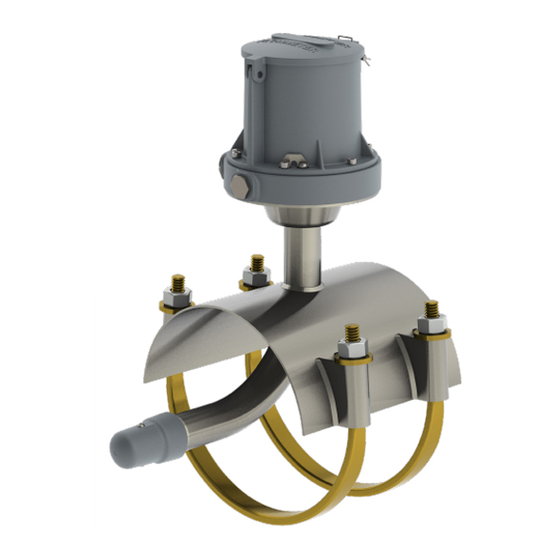
- Page 1 McMag 2000™ Battery Powered Electromagnetic Flow Meter Installation, Operation and Maintenance Manual 30124-77 Rev. 1.9 September 14, 2022...
-
Page 2: Table Of Contents
Contents SAFETY SYMBOLS AND WARNINGS . . . . . . . . . . . . . . . . . . . . . . . . . . . . . . . . . . . . . . . . . . . . . . . . . . . . . . . . . . 1 1 .0 INTRODUCTION . -
Page 3: Safety Symbols And Warnings
When installing, operating, and maintaining McCrometer equipment where hazards may be present, you must protect yourself by wearing Personal Protective Equipment (PPE) and be trained to enter confined spaces. Examples of confined spaces are manholes, pumping stations, pipelines, pits, septic tanks, sewage digesters, vaults, degreasers, storage tanks, boilers, and furnaces. -
Page 4: Introduction
Factory for any circumstances encountered which are not covered in this manual. All McCrometer products are tested and inspected during manufacture and prior to shipping. An inspection should be performed at the time of unpacking to detect any damage that might have occurred during shipment. WARNING! Incorrect installation or removal of meters can result in serious injury or death . -
Page 5: Sensor Location
Preparing for a New Installation 3 .2 Sensor Location Adjoining pipe must be adequately supported, and the area around the sensor should provide sufficient drainage to prevent flooding the converter or conduits. The location chosen should provide room to read the display and be free from harsh electrical noise from adjacent equipment, cables, RFI, or EMI. -
Page 6: Flow Meter Installation
The McMag 2000 is a saddle type meter. It may be installed The McMag2000 generally does not require directly onto an existing pipe. Follow these steps for a new NOTE grounding, particularly when the piping itself flow meter installation. -
Page 7: Replacing An Existing Mc Propeller Saddle Meter
Installation instructions can be found in a separate 2000 document, 30125-39, Flow Straightener Installation, which can be found on the McCrometer Web site. After installation, the converter must be configured for use with one of three types of flow straighteners. See section 9.0 for configuration. 4 .4... - Page 8 Refer to Figure 2 and Figure 3 for the conversion procedure. Removing the flow meter Screws / Washers Remove the flow meter that will be converted to an McMag2000. ProComm GO Remove all parts from the saddle. Keep the saddle, register U-bolts and U-Bolt nuts/washers. All other parts will not be used.
- Page 9 Flow Meter Installation Re-inserting the flow meter 17. Loosen and remove the nuts and washers from the straps. Remove the straps from the saddle. 18. Apply lubrication to the gasket and inner diameter of U-bolts with MolyKote lubricant or equivalent. 19.
-
Page 10: Internal Wire Connection
INTERNAL WIRE CONNECTION 5 .0 INTERNAL WIRE CONNECTION This section describes cable and wire harness connection inside the converter. Section 6.0 describes wire connection for all peripherals outside of the converter, including pulse output and external power options. 5 .1 Cable Gland Assignment for Wiring Harnesses Port assignment 1 - Outputs... -
Page 11: Wiring Diagrams
INTERNAL WIRE CONNECTION 5 .3 Wiring Diagrams TERMINAL BLOCK ASSIGNMENTS ATTACHES TO Coils Harness BLACK CHASSIS LUG Terminal Port Wire Color YELLOW Green/Yellow Yellow Chassis Lug Black GREEN / YELLOW Electrodes Harness Terminal Port Wire Color PINK BLACK Green/Yellow BLUE Blue GREEN / YELLOW Black... -
Page 12: Optional Smart Output Hook Up
(Figure 7) • Signals and associated wire colors in the McCrometer SmartOutput™ interface cable are identified together in the top row of the table at right. • Corresponding wire colors for transceivers from each compatible AMI vendor are identified in the columns under the top row. -
Page 13: Quick Connect Cabled Ends (Optional)
Quick Connect Cabled Ends (Optional) IMPORTANT Connections to the sensor must be made with cable supplied by McCrometer specifically for that purpose. Do not substitute the supplied cable with other types of cable, even for short runs. For repairs or added lengths of cable, the entire cable between the sensor and the converter must be replaced. -
Page 14: Power Options
EXTERNAL WIRE CONNECTION 6 .3 Power Options Depending on output options and specific application position, you may choose to add additional power options to the battery powered converter. Additionally, you have the option of connecting external power of 10-32VDC or 100-240VAC. 6 .4 DC Power Cable (Optional) The cable contains wiring for both the optional 10-32VDC power to the meter, and the 4-20mA output from the meter. -
Page 15: Battery Installation And Replacement
BATTERY INSTALLATION AND REPLACEMENT ProComm GO Battery Installation and Replacement 7 .0 BATTERY INSTALLATION AND REPLACEMENT Battery Installation and Replacement Procedure for the ProComm GO Converter This procedure applies to all ow meters with the ProComm WARNING GO converter. It describes how to install batteries in a new EXPLOSION HAZARD. - Page 16 ProComm GO Battery Installation and Replacement BATTERY INSTALLATION AND REPLACEMENT II. Removing the batteries Unplug tall connectors to sensor, outputs, and Loosen the captive screws opposite of the hinge and power. lift the battery cover. Hinge Hinge screws Connectors Unplug the batteries. Cut the two zip ties securing the batteries.
- Page 17 ProComm GO Battery Installation and Replacement BATTERY INSTALLATION AND REPLACEMENT III. Installing the batteries and restoring the power Cut the zip tie holding the 10. Pass the new zip tie through the 11. Wrap the new zip tie around the dry pack to the hinge on the slots in the internal hinge.
- Page 18 Copyright © 2022 McCrometer, Inc. All printed material should not be changed or altered without permission of McCrometer. Any published pricing, technical data, and instructions are subject to change without notice. Contact your McCrometer representative for current pricing, technical data, and instructions.
-
Page 19: Operation
General The flow meter comes pre-configured from the factory based on the installation parameters provided to McCrometer at the time of order. Other than activating the display, there is nothing required of the user for the basic operation of the flow meter. -
Page 20: Converter Configuration
This is only a summary of the configuration tool’s functionality. The software has complete set-up and operation instructions included. The software can be downloaded from the McCrometer Web site. Software Operation Remove the cap that protects the USB port and plug in a mini USB type B cable. -
Page 21: 10 .0 Error Messages For Troubleshooting
ERROR MESSAGES FOR TROUBLESHOOTING 10 .0 ERROR MESSAGES FOR TROUBLESHOOTING DISPLAY MESSAGE Troubleshooting BAT LOW Battery replacement Kit is needed to replace batteries. The batteries Should last approximately 6-9 months from the time the warning is shown. 420 ERR The 4-20 circuit is not wired correctly. Check the wiring diagram and ensure 9-30VDC power is supplied to the circuit. -
Page 22: 11 .0 Specifications
Specifications Speci cation Sheet McMag Flow Meter 2000™ 11 .0 SPECIFICATIONS Flow Meter Speci cations Physical Speci cations Measurement Volumetric ow in lled ow conduits 4” to 12” utilizing saddle installed sensor. Flow Method indication in English Standard or Metric units Directionality Single direction Pipe Sizes... - Page 23 SPECIFICATIONS ProComm Specifications 9.0 SPECIFICATIONS ProComm GO Converter Specifications Physical Speci cations Electronic Housing Diecast aluminum, powder coated enclosure w/ tamper resistant seal, 6½” x 6½” x 43/8” tall Converter See page 21for meter mount and remote mount converter dimensions. Dimensions Battery: Standard: three 3.6V lithium-thionyl chloride (Li-SOCI2) D size...
- Page 24 Specifications ProComm GO Converter Specifications (cont .) SPECIFICATIONS ProComm Gallons Barrel (42G) MH1 Miners Inch Hour Cubic Feet Barrel (46G) (11.22G) Acre Feet Barrel (55G) MD1 Miners Inch Day (11.22G) CUM Cubic Meters Imperial Gallon MH9 Miners Inch Hour (9G) Totalizer Units Liters Acre Inch...
-
Page 25: 12 .0 Dimensions And Weights
Contact McCrometer Customer Service Department and ask for a Return Authorization (RA) number. Copyright © 2022 McCrometer, Inc. All printed material should not be changed or altered without permission of McCrometer. Any published pricing, technical data, and instructions are subject to change without notice. Contact your McCrometer representative for current pricing, technical data, and instructions. -
Page 26: Warranty Statement
The batteries and their con guration are speci c IN LIEU OF ANY AND ALL OTHER WARRANTIES OF to the Dura Mag ow meter and only McCrometer batteries QUALITY OR PERFORMANCE, EXPRESS, IMPLIED OR can be used. Any use of batteries other than those supplied STATUTORY, INCLUDING, WITHOUT LIMITATION, ANY from McCrometer will void the above Warranty. - Page 27 ™ Copyright © 2022 McCrometer, Inc. All printed material should not be changed or altered without permission of McCrometer. Any published pricing, technical data, and instructions are subject to change without notice. Contact your McCrometer representative for current pricing, technical data, and instructions.
Need help?
Do you have a question about the McMag2000 and is the answer not in the manual?
Questions and answers