
Subscribe to Our Youtube Channel
Related Manuals for Esse-ti HELPY 2W-V


Summary of Contents for Esse-ti HELPY 2W-V
- Page 1 Alarm system for elevators compliant with the European Standard EN 81-28:2018 HELPY 2W-V 12V M/MK QUICK GUIDE 7IS-80484 01/03/2021...
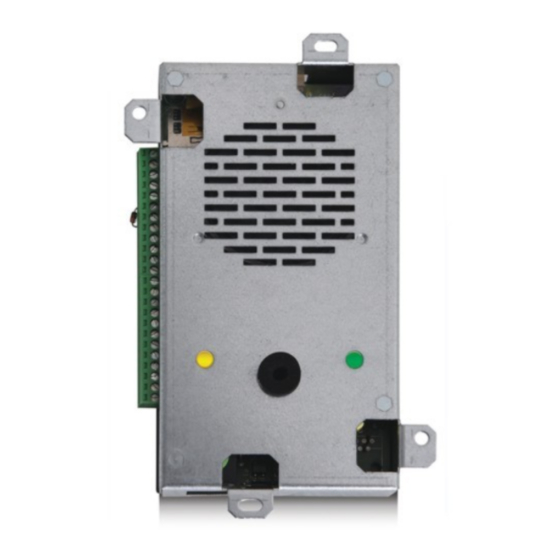
- Page 2 DESCRIPTION Autodialer specifically designed for retrofitting behind the elevator car panel. Connector for Esse-ti power supply (12 Vdc) Micro SD Card slot Device status LED Serial port for PC connection Reset pushbutton Terminal blocks G Built-in loudspeaker Built-in microphone RJ11 connector for local telephone...
-
Page 3: Terminal Blocks
TERMINAL BLOCKS Power supply input 12 Vdc Negative Given alarm indicator light Received alarm indicator light 12 Vdc output (max. 100 mA) Common terminal for inputs AL1 and IN1 Negative Alarm input Alarm input 2 / Auxiliary input / Reset input Filter input / Reset input ALT2... - Page 4 Note: a 2W speaker unit allows to realize an independent voice point with dedicated pushbutton and indicator lights. Note: a passive speaker unit must be connected to the Helpy 2W-V’s built-in speaker unit or to another 2W speaker unit and allows to double it.
- Page 5 Given alarm indicator light (light negative pole) AL1— Alarm input Auxiliary input / Alarm input / Filter input AL1+ Alarm input BUS— Bus for connecting Helpy 2W-V BUS+ Bus for connecting Helpy 2W-V only for some models CONNECTING THE SPEAKER UNITS Page 5...
- Page 6 Terminal blocks for connecting passive speaker unit ALT2 Output for connecting loudspeaker of passive speaker unit MIC2 Input for connecting microphone of passive speaker unit or single microphone — Negative Microphone DIP switch The DIP switch allows to assign an ID (01~16) to each 2W speaker unit connected to the bus.
- Page 7 CONNECTING THE EMERGENCY CALL BUTTONS Car pushbutton Passive speaker unit pushbuttons CONNECTING THE EMERGENCY CALL BUTTONS Page 7...
- Page 8 2W speaker unit pushbuttons It is possible to connect external pushbuttons to 2W speaker units without built- in pushbutton following the diagrams shown below. Page 8 CONNECTING THE EMERGENCY CALL BUTTONS...
- Page 9 CONNECTING THE FILTER INPUT CONNECTING THE FILTER INPUT Page 9...
- Page 10 CONNECTING THE INDICATOR LIGHTS The GIVEN ALARM INDICATOR LIGHT (yellow) switches on after pressing the emergency button to indicate the beginning of the alarm procedure. The RECEIVED ALARM INDICATOR LIGHT (green) switches on when the alarm call is answered. 2W speaker unit indicator lights It is possible to connect external indicator lights to 2W speaker units without built-in indicator lights following the diagrams shown below.
-
Page 11: Other Connections
ONNECTING THE AUXILIARY INPUTS Helpy 2W-V It is possible to configure the AL2 input of Helpy 2W-V as auxiliary input. Connect the external contact to AL2 terminal. Note: the AL2 input can be configured either as normally open or closed. -
Page 12: Wiring Diagrams
WIRING DIAGRAMS IRING DIAGRAM WITH SPEAKER UNITS ON CAR TOP AND IN THE PIT Page 12 WIRING DIAGRAMS... - Page 13 IRING DIAGRAM WITH PASSIVE SPEAKER UNITS WIRING DIAGRAMS Page 13...
- Page 14 IRING DIAGRAM WITH LANDING FLOORS Page 14 WIRING DIAGRAMS...
- Page 15 MINIMUM OPERATIONS TO VERIFY PROPER INSTALLATION 1. PROGRAMMING Access to programming: lift the local telephone handset and dial The programming activated message will be heard. Program a telephone number for the emergency-call alarm: dial <telephone number> Record the identification message of the specific elevator, which is meant to contain all necessary information concerning the elevator location: dial and, after the “Correct”...
-
Page 16: Resetting The Alarm
Press If the reset input is not closed within 6 hours, the alarm is automatically ended. Note: the reset input can be configured with the “Helpy 2W-V inputs setting” programming (code 55). Note: in case it should not be possible to stop the alarm procedure remotely (i.e. - Page 17 * <Password> #. Pressing longer (10 seconds) Allows to reset the device. By pressing longer, the Helpy 2W-V will be re-started with no need to disconnect the power supply. Note: it is also possible to reset the device through the code 995*0#.
-
Page 18: Basic Programming
< INSTALLER or OPERATOR PASSWORD > EXITING THE PROGRAMMING (factory default: SOURCE RECEIVER emergency- — call button battery USER alarms * periodic automatic test ESSE-TI call * … (X..X = 2W speaker telephone TELEPHONE unit connection number, NUMBERS failure alarm (position max. 20 (INST) from 01 to digits;... -
Page 19: Listen To Messages
(max. 25 s) identification LISTEN TO message MESSAGES (listen) (INST/OPER) courtesy message HELPY 2W-V BUILT-IN (ID, from 01 to 99; SPEAKER UNIT 01=Helpy 2W-V installed in the cabin) (INST) LISTEN TO THE ID DEVICES OPERATING OVER THE BUS (INST) PROGRAMMING Page 19... -
Page 20: Low Battery Alarm
BASIC PROGRAMMING LOW BATTERY disabled alarm ALARM (INST) enabled alarm REPLACE disabled alarm BATTERY ALARM (with Esse-ti power supply) enabled alarm (INST) Frequency (days, from 1 to 9; factory default 3) Time (hhmm; from 0000 to 2359) AUTOMATIC TEST automatic test disabled... -
Page 21: Advanced Programming
2=1 hour NOTIFICATION 1=emergency-call) 3=1 day) (INST) AL2=alarm input / IN1=filter input AL2=auxiliary input / IN1=filter input HELPY 2W-V INPUTS SETTING AL2=reset input / IN1=filter input (INST) AL2=alarm input / IN1=reset input AL2=auxiliary input / IN1=reset input 2W SPEAKER speaker... -
Page 22: Filter Bypass
ADVANCED PROGRAMMING NO EXTERNAL POWER SUPPLY disabled alarm ALARM (with Esse-ti enabled alarm with XX minutes delay power supply) (from 01 to 99) (INST) 2W SPEAKER disabled alarm UNIT DIAGNOSTIC ALARM enabled alarm (INST) 2W SPEAKER disabled alarm UNIT CONNECTION... - Page 23 ADVANCED PROGRAMMING PLAYBACK OF never “COMMUNICA- TION ACTIVA- TED” MESSAGE only in case of remote connection WHEN THE SPEAKER UNIT IS ACTIVATED always (INST) two-way communication established after input of TWO-WAY "Communication activation" code COMMUNICATION automatic two-way communication established MODE DURING after messages AN ALARM (INST)
- Page 24 ADVANCED PROGRAMMING (country: 00 IT/SM/AL/BA/GM/MK/MT/NO, 01 GB/AE, 02 DE/LB/LU, 03 FR/GP/GF, 04 PL, 05 PT, 06 RU/BY, 07 ES/AD/CY, 08 BG/BR/KY/ DK/ID/IR/IS/KW/MO/MW/MX/PY/UY/VE/YE/ZM/ TONE DECODER FO/LR, 10 HR, 11 GR/EE/FI, 12 NL/AW/VU, (INST) 13 SI, 14 HU, 15 IL, 16 AT, 17 AU/IE, 18 CH, 19 CN, 20 US/CA/JM/AI/AG/BB/BM/VG/DM/MS/ KN/TT/TC 21 BE, 22 QA, 23 SE, 24 IN, 25 TR, 26 CZ/SK/LT/MD, 27 TN/SA, 28 DZ, 29 MA,...
-
Page 25: Relay Setting
ADVANCED PROGRAMMING CLI CALL DURATION (seconds, from 00 to 99; factory default 10) (CLI) AUTOMATIC (ring number, from 1 to 9; ANSWER 0=disabled; factory default 2) (INST) OPERATION programming mode MODE AFTER AUTOMATIC ANSWER direct connection with the car (INST) CONNECTION DURATION AFTER AUTOMATIC... - Page 26 Local programming via e-stant software It is possible to program Helpy 2W-V via computer by using the USB/serial proprietary cable and the dedicated e-stant software. e-stant software also allows to: - update the firmware of the Helpy 2W-V...
-
Page 27: Local Use
<TELEPHONE NUMBER> DOOR OPENER RELAY Use remotely with Helpy 2W-V at rest Call Helpy 2W-V and wait for a response. Listen to the elevator identification message, if present. Dial: to speak with the cabin speaker unit (ID 01) - Page 28 Dial <password> (factory default: ) to access programming. All of the programming and functions below can now be performed: USE REMOTELY WITH HELPY 2W-V AT REST PROGRAMMING … CABIN SPEAKER UNIT (ID 01) SPEAKER UNIT (ID 02) CONVERSATION...
-
Page 29: Device Status Led
SIGNALS Device status LED Normal operation (no alarm) Alarm Voice connection Battery disconnected or low battery (max. 1-hour operation in idle state) 2W speaker unit connection error or bus problem Absence of telephone line Button failure SIGNALS Page 29... - Page 30 Given alarm indicator light (yellow) Alarm Received alarm indicator light (green) Voice connection Missed test call notification The Given alarm indicator light and the Received alarm indicator light flash in opposition to indicate the failure of the automatic test call. The flashing sequence ends after the next successful test call or emergency call.
-
Page 31: Eu Declaration Of Conformity
EU DECLARATION OF CONFORMITY Hereby, Esse-ti S.r.l. declares that the equipment type Helpy 2W-V is in compliance with Directives 2014/30/EU - 2014/33/EU - 2014/35/EU. The full text of the EU declaration of conformity is available from the following Internet address: https://www.esse-ti.it/en/dichiarazioni-di-conformita... - Page 32 Esse-ti S.r.l. Via G. Capodaglio, 9 62019 Recanati (MC) – ITALY Tel. +39 071 7506066 Fax +39 071 7506057 www.esse-ti.it support@esse-ti.it...
Need help?
Do you have a question about the HELPY 2W-V and is the answer not in the manual?
Questions and answers