
Related Manuals for YOKOGAWA EJX110B


Summary of Contents for YOKOGAWA EJX110B
- Page 1 User’s Manual EJX110B, EJX310B and EJX430B Differential Pressure and Pressure Transmitters IM 01C27B01-01EN IM 01C27B01-01EN 16th Edition Y okogawa Electric Corporation...
-
Page 2: Table Of Contents
Toc-1 EJX110B, EJX310B and EJX430B Differential Pressure and Pressure Transmitters IM 01C27B01-01EN 16th Edition Contents Introduction ....................1-1 Safe Use of This Product ................. 1-2 Radio Wave ......................1-3 Warranty ......................1-4 Trademarks ......................1-4 Control of Pollution Caused by the Product ..........1-5 Handling Cautions .................. - Page 3 Toc-2 Swapping the High/Low-pressure Side Connection ........4-3 4.4.1 Rotating Pressure-detector Section 180° ......... 4-3 4.4.2 Using the Configuration Tool .............. 4-4 Rotating Transmitter Section ................4-4 Changing the Direction of Integral Indicator ..........4-5 Changing the direction of the antenna ............4-5 Installing Impulse Piping ................. 5-1 Impulse Piping Installation Precautions ............
- Page 4 Toc-3 8.3.5 Unit ....................8-11 8.3.6 Range Change ................. 8-11 8.3.7 Output Mode ..................8-11 8.3.8 Output Signal Low Cut Mode Setup ..........8-11 8.3.9 Impulse Line Connection Orientation Setup ........8-12 8.3.10 Integral Indicator Display Mode ............8-12 8.3.11 Integral Indicator Scale Setup ............8-12 8.3.12 Unit for Displayed Temperature ............8-12 8.3.13 Unit for Displayed Static Pressure ........... 8-13 8.3.14 Zero Point Adjustment and Span Adjustment ........
-
Page 5: Introduction
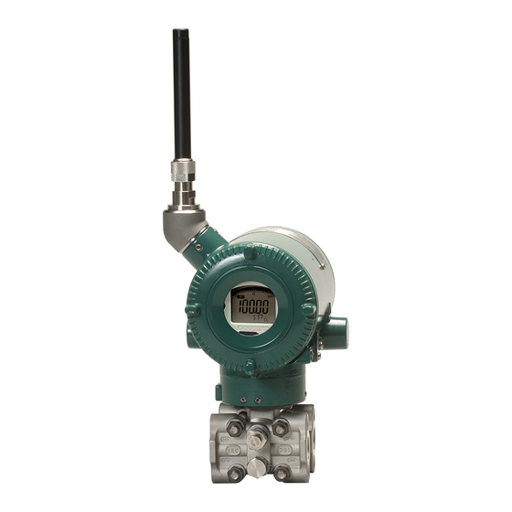
Unless otherwise stated, the illustrations in this that postponement of revisions will not cause manual are of the EJX110B differential pressure difficulty to the user from a functional or transmitter with a detachable antenna type. performance standpoint. Users of the other models and specifications • Yokogawa assumes no responsibilities for this should bear in mind that certain features of their product except as stated in the warranty. instrument will differ from those shown in the • If the customer or any third party is harmed by illustrations of the EJX110B. the use of this product, Yokogawa assumes no responsibility for any such harm owing to MODEL SUFFIX any defects in the product which were not EJX110B predictable, or for any indirect damages. --8* EJX310B --9* • The following safety symbols are used in this EJX430B manual and on the product: Regarding This Manual ... -
Page 6: Safe Use Of This Product
If these instructions are not heeded, the protection NOTE provided by this instrument may be impaired. In this case, Yokogawa cannot guarantee that the Draws attention to information essential for instrument can be safely operated. Please pay understanding the operation and features. special attention to the following points: (a) Installation Functional grounding terminal • This instrument may only be installed by an... -
Page 7: Radio Wave
(e) Modification Before using this instrument, ensure that neither a premises radio station nor specified • Yokogawa will not be liable for malfunctions or low power radio station for mobile object damage resulting from any modification made identification systems is in use nearby. to this instrument by the customer. If this instrument causes radio wave (f) Product Disposal interference to a wireless station for mobile • The instrument should be disposed of in object identification systems, promptly accordance with local and national legislation/ change the frequency being used or turn regulations. -
Page 8: Warranty
In this document, trademarks or registered the quotation presented to the purchaser at the trademarks are not marked with “™” or “®”. time of purchase. Problems occurring during Product names and company names in this the warranty period shall basically be repaired document are trademarks or registered trademarks free of charge. of the respective companies • If any problems are experienced with this instrument, the customer should contact the Yokogawa representative from which this instrument was purchased or the nearest Yokogawa office. • If a problem arises with this instrument, please inform us of the nature of the problem and the circumstances under which it developed, including the model specification and serial number. Any diagrams, data and other information you can include in your communication will also be helpful. • The party responsible for the cost of fixing the problem shall be determined by Yokogawa following an investigation conducted by Yokogawa. -
Page 9: Control Of Pollution Caused By The Product
<1. Introduction> Control of Pollution Caused by the Product This is an explanation for the product based on “Control of Pollution caused by Electronic Information Products” in the People’s Republic of China. 電子情報製品汚染制御管理弁法 (中国版RoHS) 产品中有害物质或元素的名称及含量 产品中有害物质或元素的名称及含量 有害物质 型号 部件名称 铅 汞 镉 六价铬 多溴联苯 多溴二苯醚 (Pb) (Hg) (Cd) (Cr(VI)) (PBB) (PBDE) 壳体 × ○ ○ ○ ○ ○ EJX-B series 膜盒组件 ×... -
Page 10: Handling Cautions
No antenna is provided for Amplifier Antenna housing code 9. It enables confirming the specifications of purchased products and user’s manuals. Bolt For more details, please refer to the following Process connector URL. Process connector gasket https://www.yokogawa.com/qr-code U-bolt QR Code is a registered trademark of DENSO WAVE INCORPORATED. Unpacking Keep the transmitter in its original packaging to prevent it from being damaged during shipment. Mounting bracket (L type) Do not unpack the transmitter until it reaches the U-bolt nut installation site. -
Page 11: Storage
<2. Handling Cautions> Storage Selecting the Installation Location The following precautions must be observed when storing the instrument, especially for a long period. The transmitter is designed to withstand severe environmental conditions. However, to ensure (a) Select a storage area which meets the following that it will provide years of stable and accurate conditions: performance, take the following precautions when • It is not exposed to rain or subject to water selecting the installation location. seepage/leaks. • Vibration and shock are kept to a minimum. (a) Wireless Communication • It has an ambient temperature and relative humidity within the following ranges. NOTE Ambient temperature: –40 to 85°C The installation location of this transmitter must –30 to 80°C LCD visible range meet the following conditions: Relative humidity: Adjust the direction of the antenna to be... -
Page 12: Pressure Connection
<2. Handling Cautions> Restrictions on Use of Radio (b) Ambient Temperature Avoid locations subject to wide temperature Transceivers variations or a significant temperature gradient. If the location is exposed to radiant heat from IMPORTANT plant equipment, provide adequate thermal insulation and/or ventilation. Although the transmitter has been designed to resist high frequency electrical noise, if a radio (c) Ambient Atmosphere transceiver is used near the transmitter or its Do not install the transmitter in a corrosive external wiring, the transmitter may be affected atmosphere. If this cannot be avoided, there by high frequency noise pickup. To test this, start must be adequate ventilation. out from a distance of several meters and slowly (d) Shock and Vibration approach the transmitter with the transceiver... -
Page 13: Installation Of An Explosion-Protected Instrument
Installation of an Explosion- 5) After completing the test and being very careful Protected Instrument not to touch exposed conductors disconnect the insulation tester and connect a 100 kΩ resistor If a customer makes a repair or modification to an between the grounding terminal and the short- intrinsically safe instrument and the instrument is circuiting battery connection terminals. Leave not restored to its original condition, its intrinsically this resistor connected at least one second to safe construction may be compromised and the discharge any static potential. Do not touch the instrument may be hazardous to operate. Please terminals while it is discharging. contact Yokogawa before making any repair or modification to an instrument. NOTE CAUTION When storing the instrument with a battery pack, it is recommended to put the instrument in This instrument has been tested and certified Deep Sleep mode to conserve the batteries. For as being intrinsically safe. Please note that details on how to switch to Deep Sleep mode, severe restrictions apply to this instrument’s refer to subsection 8.3.16 “Switching to Deep construction, installation, external wiring, Sleep Mode”. maintenance and repair. A failure to abide by these restrictions could make the instrument a • Dielectric Strength Test hazard to operate. -
Page 14: Fm Approval
WARNING – DO NOT OPEN WHEN CL II, III, DIV 1, 2 ATMOSPHERE IS PRESENT WARNING – USE ONLY BATTERY PACK YOKOGAWA F9915MA OR F9915NS WARNING – THE BATTERY PACK CAN BE REPLACED IN A HAZARDOUS LOCATION. THE BATTERY PACK HAS SURFACE RESISTIVITY GREATER THAN 1G OHM AND MUST BE PROPERLY INSTALLED IN THE ENCLOSURE OF THE TRANSMITTER. -
Page 15: Csa Certification
Groups A,B,C,D,F,G FROM ANTENNA. Groups A,B,C,D,E,F,G Class III, Division 1 DO NOT OPEN WHEN CL II, III, DIV 1,2 F0205.ai Note 3. Battery Pack ATMOSPHERE IS PRESENT. • Use only YOKOGAWA battery pack 2.8.2 CSA Certification F9915MA or F9915NS. Caution for CSA Intrinsically safe type. (Following Note 4. Special Conditions for safe use contents refer to “DOC No. ICS030”) • Potential electrostatic charging hazard - secure distance of 100mm from antenna. - Page 16 <2. Handling Cautions> Note 2. Specific condition of use Yokogawa Electric Corporation EJX−L Series Model When the equipment is mounted in an area Control drawing Title where the use of Category 1 G equipment is IKE037-A80 2020-09-02 Page Revision Date required, it shall be installed in such a way that, Amplifier housing code 7 Amplifier housing code 8 and 9...
-
Page 17: Iecex Certification
Tamb.: -50 TO 70°C MAX PROCESS TEMP.: 120°C POTENTIAL ELECTROSTATIC CHARGING HAZARD - SECURE DISTANCE source due to impact and/or friction sparks is WARNING OF 100MM FROM ANTENNA. USE ONLY BATTERY PACK YOKOGAWA F9915MA OR F9915NS. POTENTIAL ELECTROSTATIC CHARGING HAZARD - SEE USER'S MANUAL. excluded. F0208.ai Precaution shall be taken to minimize the risk MODEL: Specified model code. -
Page 18: Emc Conformity Standards
(*1, *2) (*1) Antenna connector vessel section of directive 2014/68/EU, which corresponds to Article 4, Paragraph 3 of PED, Transmitter Transmitter denoted as Sound Engineering Practice (SEP). Battery Pack Battery Pack • EJX110B-MS, EJX110B-HS, *1: These apparatus are simple apparatus. EJX110B-VS, EJX510B-D, and *2: Arrester may not be connected. EJX530B-D can be used above 200 bar and Notes: The following conditions must be met for the antenna connector (total Li of simple apparatus) + (total Lc) ≤ 1 mH therefore considered as a part of a pressure (total Ci of simple apparatus) + (total Cc) ≤ 1 μF The temperature class of Antenna and Arrester must be determined from Po= 20 mW at Antenna retaining vessel where category III, Module H Connector. -
Page 19: Low Voltage Directive
(3) Operation for Radio and CAUTION Telecommunication • The temperature and pressure of fluid should Please confirm that a installation region fulfils a be maintained at levels that are consistent standards, require additional regulatory information with normal operating conditions. and approvals, contact to Yokogawa Electric • The ambient temperature should be Corporation. maintained at a level that is consistent with normal operating conditions. 2.12.1 Radio Equipment Directive (RE) • Please take care to prevent water hammer Hereby, Yokogawa Electric Corporation declares and the like from inducing excessive that the radio equipment type EJXB is in pressures in pipes and valves. -
Page 20: Industry Canada (Ic) Compliance
2-11 <2. Handling Cautions> 2.12.3 Industry Canada (IC) compliance Le présent émetteur radio IC Number 8999A-WIC001 / 8999A-WIC013 a été This equipment contains transmitter module IC: approuvé par Industrie Canada pour fonctionner 8999A-WIC001 / 8999A-WIC013 avec les types d’antenne énumérés ci-dessous This device complies with ISED’s applicable et ayant un gain admissible maximal. Les types license-exempt RSSs. Operation is subject to the d’antenne non inclus dans cette liste, et dont le following two conditions: (1) this device may not gain est supérieur au gain maximal indiqué, sont cause interference, and (2) this device must accept strictement interdits pour l’exploitation de l’émetteur. -
Page 21: Component Names
<3. Component Names> Component Names Vertical impulse pipimg type Preccure-detector section Terminal box cover Cover flange Horizontal impulse piping type Process connector (Note1) Antenna Ground terminal Zero-adjustment screw Vent plug Process connction CPU assembly Integral indicator Drain plug ● Terminal configuration RF assembly (External powered type) Power supply... -
Page 22: Installation
<4. Installation> Installation Precautions ■ When mounting the bracket on the transmitter, tighten the (four) bolts that hold the transmitter Before installing the transmitter, read the cautionary with a torque of approximately 39 N·m {4kgf·m}. notes in section 2.4, “Selecting the Installation Location.” For additional information on the ambient conditions allowed at the installation location, refer to subsection 11.1 “Standard Specifications.” 57 mm 54 mm 51 mm F0401.ai NOTE Figure 4.1 Process Connector Impulse Piping Connection Distances for Differential To connect this transmitter to the Field Wireless Pressure Transmitters Network, information for connecting to the field wireless devices needs to be set beforehand. CAUTION Refer to 7.4 “Connecting to the Field Wireless Network.” When the suffix code of the mounting bracket is “B,” make sure to put the spacer between the IMPORTANT... - Page 23 <4. Installation> Vertical pipe mounting (Process connector upside) Horizontal pipe mounting (Process connector upside) Mounting bracket Mounting bracket 50 mm (2-inch) pipe U-bolt nut 50 mm (2-inch) pipe U-bolt nut U-bolt U-bolt Transmitter Transmitter mounting bolt mounting bolt Vertical pipe mounting (Process connector downside) Horizontal pipe mounting (Process connector downside) Transmitter mounting bolt Transmitter mounting bolt...
-
Page 24: Changing The Process Connection
Changing the Process Swapping the High/Low- Connection pressure Side Connection The transmitter is shipped with the process IMPORTANT connection specified at the time of ordering. To change the process connection, the drain (vent) This section is applicable only for EJX110B plug must be repositioned. differential transmitters, and not applicable for gauge or absolute pressure transmitters. To reposition a drain (vent) plug, refer to Figure 4.4 and use a wrench slowly and gently to unscrew it. Then, remove and remount it on the opposite 4.4.1 Rotating Pressure-detector Section side. Wrap sealing tape around the drain (vent) -
Page 25: Using The Configuration Tool
<4. Installation> Rotating Transmitter Section 4.4.2 Using the Configuration Tool This method is applicable only to the model WARNING EJX110B. With a configuration tool, you can change which Intrinsic safe type transmitters must be, as a rule, process connection is used as the high-pressure do not rotate transmitter section if it is powered. side without mechanically rotating the pressure- In case you need to rotate when the transmitter detector section 180 as described in subsection is powered, using gas detector and confirm no 4.4.1. To change, call up the ‘H/L_SWAP’ parameter existence of explosive gas before rotating. and select REVERSE (right side: low pressure; left side: high pressure) or select NORMAL to change The transmitter section can be rotated back to normal (right side: high pressure; left side: low pressure). approximately 360° (180° to either direction or 360° to one direction from the original position at NORMAL shipment, depending on the configuration of the instrument.) It can be fixed at any angle within Output above range. 1) Remove the five setscrews that fasten the transmitter section and capsule assembly, using the Allen wrench. Input 2) Rotate the transmitter section slowly and stop it at designated position. -
Page 26: Changing The Direction Of Integral Indicator
<4. Installation> Changing the direction of Vertical impulse piping type the antenna Pressure-detector section Adjust the direction of the antenna to be in the upright position. Figure4.8 shows factory setup antenna position. If the transmitter is installed to vertical impulse piping, follow the procedure below and change the antenna position. 1) Loosen the two mounting screws at the bottom of the antenna by using a 2.5 mm Allen wrench (see Figure 4.8). Transmitter section The screws might come off and be lost if loosened too much; loosen the screws by about Horizontal impulse piping type three rotations. Transmitter section 2) Press forward and down 90 degrees by rotating the axis at the bottom of the antenna. -
Page 27: Installing Impulse Piping
<5. Installing Impulse Piping> Installing Impulse Piping Impulse Piping Installation (2) Changing the Process Connector Piping Connections (Figure 4.1) (for differential Precautions pressure transmitters) The impulse piping that connects the process The impulse piping connection distances can be outputs to the transmitter must convey the process changed between 51 mm, 54 mm and 57 mm by pressure accurately. If, for example, gas collects changing the orientation of the process connectors. in a liquid-filled impulse line, or the drain for a This is convenient for aligning an impulse line with a gas-filled impulse line becomes plugged, it will process connectors. not convey the pressure accurately. Since this will cause errors in the measurement output, select (3) Tightening the Process Connector the proper piping method for the process fluid Mounting Bolts (gas, liquid, or steam). Pay careful attention to the... - Page 28 <5. Installing Impulse Piping> Pipe-Mounting Type 3-Valve Manifold Direct-Mounting Type 3-Valve Manifold (Figure 5.2) (Figure 5.3) 1) Screw nipples into the connection ports on the 1) Mount the 3-valve manifold on the transmitter. transmitter side of the 3-valve manifold, and (When mounting, use the two gaskets and the into the impulse piping connecting ports on four bolts provided with the 3-valve manifold. the process connectors. (To maintain proper Tighten the bolts evenly.) sealing, wind sealing tape around the nipple 2) Mount the process connectors and gaskets threads.) on the top of the 3-valve manifold (the side on 2) Mount the 3-valve manifold on the 50 mm (2- which the impulse piping will be connected).
-
Page 29: Routing The Impulse Piping
<5. Installing Impulse Piping> 5.1.2 Routing the Impulse Piping (3) Impulse Piping Slope The impulse piping must be routed with only an (1) Process Pressure Tap Angles upward or downward slope. Even for horizontal If condensate, gas, sediment or other extraneous routing, the impulse piping should have a slope of material in the process piping gets into the impulse at least 1/10 to prevent condensate (or gases) from piping, pressure measurement errors may result. To accumulating in the pipes. prevent such problems, the process pressure taps (4) Temperature Difference Between Impulse must be angled as shown in figure 5.4 according to... -
Page 30: Impulse Piping Connection Examples
<5. Installing Impulse Piping> (7) Preventing Freezing Liguid Steam If there is any risk that the process fluid in the Orifice Condensate pot impulse piping or transmitter could freeze, use a valve steam jacket or heater to maintain the temperature of the fluid. Union or flange NOTE After completing the connections, close the valves on the process pressure taps (main 3-valve manifold valves), the valves at the transmitter (stop valves), and the impulse piping drain valves, Drain Drain so that condensate, sediment, dust and other valve plug extraneous material cannot enter the impulse F0505.ai piping. Figure 5.5 Impulse Piping Connection Examples for Differential Pressure Transmitters Impulse Piping Connection Liquid... -
Page 31: Wiring
<6. Wiring> Wiring Mounting Antenna and Wiring An antenna is not attached to the transmitter. The following provides the instructions for mounting the antenna and installing the remote antenna and wiring using antenna extension cable. IMPORTANT The antenna connector is covered with a cap at the time of delivery. Keep the cap attached Antenna connector until the installation of the antenna or antenna cables to protect the inside connection part. The unscrewed cap should be stored in order to replace it immediately after the antenna or antenna cables are removed. CAUTION To maintain the ultimate conditions of radio- frequency signal, protect the connectors of antenna, extension antenna cable, and surge F0601.ai protective device from the corrosive atmosphere Figure 6.1 Mounting the antenna... -
Page 32: Mounting External Antenna And Wiring Antenna Extension Cable
<6. Wiring> 6.1.2 Mounting External Antenna and Mounting Procedure of External Wiring Antenna Extension Cable Antenna 1. Fix the bracket by U-bolt and nut to 50 mm (2- 6.1.2.1 Mounting of External Antenna inch) pipe. 2. Fix the antenna extension cable to the bracket Mount the external antenna at the proper location 1 using the provided nut with a torque of 6 to 7 according to the wireless environment described N∙m as shown in the Figure 6.3 above. Use the in 2.4 Selecting the Installation Location. The nut which is attached to the antenna extension mounting to the pipe such as 50 mm (2-inch) pipe cable. needs to secure the enough strength to endure a 3. Screw the antenna into the antenna connector strong wind, vibration and so on. The antenna must of the antenna extension cable on the bracket be mounted vertically. Fixing of External Antenna Tighten the antenna connector with a torque of 2 to 3 N∙m. - Page 33 Protect by self-bonding tape Grounding cable Antenna extension cable 1: 3 m Antenna extension cable 1: 3 m Protect by self-bonding tape Transmitter body Transmitter body F0604.ai Figure 6.4 Wiring the antenna extension cable CAUTION Use the dedicated antenna extension cable provided by Yokogawa as accessories for the transmitters. IM 01C27B01-01EN...
-
Page 34: Mounting Of Surge Protective Device And Wiring
<6. Wiring> Grounding 6.1.2.3 Mounting of Surge Protective Device and Wiring When using the antenna extension cable with an Mount an surge protective device between the arrestor, Class C grounding with the grounding extension cables and connect the grounding cable resistance of 10 Ω is required. Always ground the to the grounding terminal of the surge protective transmitter case in accordance with national and device as required. local electrical codes. The most effective transmitter case grounding method is a direct connection to Connect the grounding cable to the grounding earth ground with minimal impedance. terminal on the transmitter body. Class C grounding with the grounding resistance of 10 Ω or less is IMPORTANT necessary. Do not share the ground with other devices. Proper grounding is necessary to maintain the function and performance of this product. When Antenna side the grounding is inadequate, the equipment may be damaged. -
Page 35: Power Supply Wiring Precautions
<6. Wiring> Power Supply Wiring Connection of the External Precautions Power Source Terminal For the external powered type, connect the power IMPORTANT supply wiring to + and − terminals. If the power supply cable has shield wires, connect the cable • All threaded parts must be treated with shield to the ground terminal. waterproofing sealant. (A non-hardening Power supply terminal + silicone group sealant is recommended.) Ground terminal • Lay wiring as far as possible from electrical noise sources such as large capacity motors or power supplies. • Remove the electrical connection dust cap before wiring. Power supply terminal – Selecting the Wiring F0608.ai Figure 6.8... -
Page 36: Operation
<7. Operation> Operation Preparation for Starting ■ Gauge/Absolute Pressure Transmitters Operation 1) Open the tap valve (main valve) to fill the impulse piping with process fluid. This section describes the operation procedure 2) Gradually open the stop valve to introduce for the EJX110B as shown in figure 7.1 (vertical process fluid into the transmitter pressure- impulse piping type, high-pressure connection: detector section. right side) when measuring the liquid flow rate, and 3) Confirm that there is no pressure leak in EJX430B as shown in figure 7.2 when measuring the impulse piping, transmitter, or other pressure. components. (b) Venting Gas from the Transmitter Pressure- NOTE detector Section Since the piping in the example of figure 7.1... -
Page 37: Zero Point Adjustment
<7. Operation> ■ Confirm that transmitter is operating Orifice properly by integral indicator. Tap valve (high pressure) If the transmitter is faulty, an error code is displayed. Tap valve (low pressure) Stop valve 3-valve manifold (low pressure) Self-diagnostic error on integral indicator Equalizing valve (Faulity transmitter) F0703.ai Stop valve Figure 7.3 Integral Indicator with Error Code (high pressure) -
Page 38: Starting Operation
<7. Operation> Starting Operation (1) When you can obtain the Low Range Value from the actual measured value of 0% After completing the zero point adjustment, follow (0 kPa, atmospheric pressure); the procedures below to start operation. Steps 1) and 2) are specific to the differential pressure ■ Using the transmitter’s zero-adjustment transmitters. screw 1) Close the equalizing valve. Before adjusting zero point, make sure followings. 2) Gradually open the low pressure stop valve. • The External zero trim parameter (External This places the transmitter in an operational Zero Trim) is “Trim on”. For details, refer to condition. - Page 39 Provisioning Example load from the Field Wireless Configurator to the Field Wireless Integrated Gateway. Store the file carefully. ■ Provisioning work ■ Connecting to a field wireless network This subsection describes provisioning work using FieldMate as the provisioning device. The action after installing the battery pack or turning Provisioning work performs provisioning for each on the power varies depending on the silence field wireless device using FieldMate and an setting. infrared adapter. If Yokogawa - recommended Mounting the battery pack or turning on the power infrared device is used for provisioning, distance automatically starts a search for the field wireless between the transmitter glass window and the network. When the Field Wireless Integrated infrared device should be within 30cm. For details of Gateway is found, the instrument enters the join Yokogawa - recommended infrared device, refer to status. subsection 9.2 “Calibration Instruments Selection”. When the field wireless gateway is not found and Perform the following provisioning tasks. a specified time based on the silence mode has elapsed, a cycle of a one-hour pause and six- • Setting provisioning information minutes search is repeated until the instrument can • Creating a provisioning information file...
-
Page 40: Shutting Down The Transmitter
<7. Operation> (a) Deep sleep NOTE If the transmitter searches the Field Wireless Network for long time at low ambient temperature condition, sometimes error “AL.70 LOWBAT” is displayed on the Integral Indicator. Even though using new batteries, it can occur. It occurs because of battery characteristics. After joining to the Field Wireless Network, this error will be cleared within one hour if battery has no failure. F0706.ai (b) Ready and pause Shutting Down the Transmitter Shut down the transmitter as follows. 1) Turn off the power or remove the battery pack or set the transmitter to deep sleep mode by the Device Configuration Tool. 2) Close the low pressure stop valve. 3) Open the equalizing valve. F0707.ai 4) Close the high pressure stop valve. (c) Confirm connecting status 5) Close the high pressure and low pressure tap valves. -
Page 41: Venting Or Draining Transmitter Pressure-Detector Section
<7. Operation> Venting or Draining Transmitter Pressure- detector Section Since this transmitter is designed to be self- draining and self-venting with vertical impulse piping connections, neither draining nor venting will be required if the impulse piping is configured appropriately for self-draining or self-venting operation. If condensate (or gas) collects in the transmitter Drain plug pressure-detector section, the measured pressure Drain screw may be in error. If it is not possible to configure the piping for self-draining (or self-venting) operation, you will need to loosen the drain (vent) screw on the When you loosen the drain screw or drain plug, the accumulated liquid will be expelled transmitter to completely drain (vent) any stagnated in the direction of the arrow. -
Page 42: Setting Parameters
Preparing Software 8.3.1 Parameter Usage and Selection 8.2.1 Softwares for the Field Wireless Before setting a parameter, please see the following Configuration Tool and the Device table for a summary of how and when each Configuration Tool parameter is used. Before using the device configuration tool, IMPORTANT confirm that CF/DD and DeviceDTM for your transmitter (wireless EJX) are installed in the device After setting and sending data with the field configuration tool. wireless configuration tool or the device Refer to the following website for the latest configuration tool, wait 30 seconds before information on CF/DD and DeviceDTM. turning off the transmitter. If it is turned off <http://www.yokogawa.com/> too soon, the settings will not be stored in the transmitter. IM 01C27B01-01EN... -
Page 43: Function Block And Menu Tree
<8. Setting Parameters> Table 8.1 Parameter Usage and Selection Item Description Tag No Sets the tag No. as Device Tag (Software Tag). Sixteen characters (alphanumeric characters, including - and •) can be set. Output The process variable and the diagnostic result can be output. Either or all of differential pressure/pressure (AI1:Process Value), static pressure (AI2:Process Value), temperature(AI3:Process Value) of capsule or amplifier and self-diagnostic information (UAPMO:Diagnostic Status) can be set to the output Range Adjust the range corresponding for 0% to 100%. The unit of the range, input value at 0% (LRV) and input value at 100% (URV) is set. Note: LRV and URV can be set within the range of -32000 to 32000. Damping time constant Damping time constant is used to reduce the large fluctuation of pressure signal and given by each Process Value Filter Time parameter for differential Pressure/pressure (AI1) and Static pressure (AI2). Output signal and integral indicator mode Sets mode for output signal and integral indicator to “linear mode” (proportional to input differential pressure) or to “Square root mode” (proportional to flow). Output signal low cut mode Used mainly to stabilize output near 0 if output signal is the square root mode. Two modes are available: forcing output to 0% for input below a specific value, or changing to proportional output for input below a specific value. Integral indicator range of scale and unit Sets one of differential pressure/pressure value, static pressure value, or temperature value for the integral indicator scale. - Page 44 <8. Setting Parameters> Online Menu (UAPMO) (Configuration) • UAP Option • UAPMO • Configuration • Hardware Write Protect • UDO • Diagnostics • Alerts • CO • Static Revision • Power Status • TRANSDUCER • Reset Energy Left • Identification •...
- Page 45 <8. Setting Parameters> Online Menu (continued) (AI1 DP) (Block Info) • Tag Description • Block Info • Block Mode • Dynamic Variables (Block Mode ) • Configuration • Mode.Target • Calibration • Mode.Actual • Others • Mode.Permitted • Mode.Normal (Process Value) (Dynamic Variables) •...
- Page 46 <8. Setting Parameters> Online Menu (continued) (AI2 SP) (Block Info) • Tag Description • Block Info • Block Mode • Dynamic Variables (Block Mode ) • Configuration • Mode.Target • Others • Mode.Actual • Mode.Permitted • Mode.Normal (Dynamic Variables) (Process Value) •...
- Page 47 <8. Setting Parameters> Online Menu (continued) (Block Info) (AI3 Temp) • Tag Description • Block Info • Block Mode • Dynamic Variables (Block Mode ) • Configuration • Mode.Target • Others • Mode.Actual • Mode.Permitted • Mode.Normal (Dynamic Variables) (Process Value) •...
- Page 48 <8. Setting Parameters> (2) Menu Tree The menu tree of the device configuration tool of our recommendation is shown below. Refer to Subsection 9.2 “Calibration Instruments Selection” for the device configuration tool of our recommendation. Menu (Online) (Device Configuration) (UAPMO) (Configuration) (Alerts) • Device Configuration • UAPMO • Configure/Setup • UAP Option • Other Faults Alert • Diagnostic • TRANSDUCER • Hardware Write Protect • Faults Non-compliance •...
- Page 49 <8. Setting Parameters> Menu (Online) Device Configuration (continued) (continued) (Block Info) (AI2 SP) • Configure/Setup • Tag Description (Block Mode) • Mode.Target • Mode.Actual • Mode.Permitted • Mode.Normal (Configuration) (Block Mode) • Block Mode • Mode.Target • Concentrator OID • Mode.Actual •...
- Page 50 <8. Setting Parameters> Menu (Online) (continued) (UAPMO) (Diagnostics) (Diagnostic) (Diagnostic Configuration) • UAPMO • Device Diagnostics • Diagnostic Status • Diagnostic.Other Faults • Diagnostic Status Detail.1 • Diagnostic.Faults Non-Compliance • Diagnostic Status Detail.2 • Diagnostic.Faults Process Influence • Diagnostic Switch •...
-
Page 51: Parameters For Wireless Communication
8-10 <8. Setting Parameters> 8.3.3 Parameters for Wireless (6) LCD display Communication The following steps describe how to set LCD display. (1) Network Information 1. On/Off of display Concentrator object block: Configuration When “Enable” in LCD Mode is selected, the Allows confirming the network information. LCD displays a set of screens to be shown and turns off for the specified time based on LCD (2) Update Time Intermittent Time, and the display keeps the CO block: Data publication period cycle repeatedly. Not selecting this parameter turns the LCD off. Sets the update time value to 0.5 to 3,600 seconds. 2. On/Off of continuous display mode The setting affects the battery life. When “Enable” is set to LCD Mode and zero is When update time is set 0 seconds, the transmitter set to LCD Intermittent Time, the LCD displays is stopped to update process variables by way continuously. -
Page 52: Unit
8-11 <8. Setting Parameters> • When changing the device information, input 8.3.8 Output Signal Low Cut Mode Setup the information based on the following limitation Low cut mode can be used to stabilize the output on the number of characters. signal near the zero point. - Message function (up to 32 characters) ( There is 10% of hysteresis at only point of TRANSDUCER block: Tag Description transition from low to high) AI1-AI3 block: Tag Description [Setup Low Cut Value] 8.3.5 Unit • Procedure to call up the Low Cutoff* display AI1 block: Low Cutoff* The unit parameter is set at the factory before shipment if specified at the time of order. Follow the Example: setup LOW_CUT of output to 15% procedure below to change the unit parameter. *Low Cutoff • Procedure to call up the Unit display (Units = (“Eu at 100%” - “Eu at 0%”) × 0.15 + “Eu at 0%” Index) [Setup Low Cut Mode] Al1 - Al3 block: SCALE: Units Index... -
Page 53: Impulse Line Connection Orientation Setup
8-12 <8. Setting Parameters> 8.3.9 Impulse Line Connection Orientation Follow the procedure described in (1) to (2) below Setup to set the integral indicator. (1) Display Selection This function reverses the impulse line orientation. Display set to Display Selection is displayed on the Follow the procedure below to assign the high integral indicator. pressure impulse line connection to the L side of the transmitter. • Procedure to call up the Display Selection display • Procedure to call up the H/L Swap display TRANSDUCER block: Display Selection TRANSDUCER block: H/L Swap The Display Selection parameter enables Select Reverse among two choices ( Normal / the differential pressure/pressure (AI1 block), Reverse) in a H/L Swap parameter. static pressure (AI2 block), and temperature Normal is chosen at the time of shipment. (AI3 block) to be displayed on the LCD. Select 8.3.10 Integral Indicator Display Mode whether or not to enable each block to be displayed It is easy to check on the LCD whether Non... -
Page 54: Unit For Displayed Static Pressure
8-13 <8. Setting Parameters> 8.3.13 Unit for Displayed Static Pressure (1) Zero Point Adjustment Follow the procedure to change the static pressure To set 0% at current input, perform unit. following procedure. Changing this parameter also changes the unit for This method is used only when the pressure at the static pressure display. bottom of measurement range is zero. • Procedure to call up the Sensor Range.Units • Procedure to call up the lower limit adjustment Index display parameter (Calibration Lowest Point). AI2 block : Sensor Range.Units Index AI1 block: Calibration Lowest Point Confirm that KPa is selected in the Sensor Set 0 to Calibration Lowest Point parameter for Range.Units Index parameter for the static differential pressure (Al1 block). - Page 55 8-14 <8. Setting Parameters> • Procedure to call up the calibration status (2) Span Adjustment parameter (Cal Status). Span Adjustment is function to change the input and AI1 block : Cal Status output characteristic that assumed the bottom value Confirm the calibration status of CAL_ (zero point) of measurement range a standard. Therefore, perform span adjustment (adjustment SUCCESS(1) using the Cal Status parameter. of the upper limit value) after zero adjustment DPharp span: 0~25.00 kPa (adjustment of bottom limit value). Actual level: 13.50 kPa Transmitter output: 13.83 kPa After adding the pressure at point of adjustment and 25.00 kPa setting pressure value as parameter, the transmitter calculates quantity of adjustment and performs...
-
Page 56: Software Write Protect
8-15 <8. Setting Parameters> • Procedure to call up the calibration status 8.3.15 Software Write Protect parameter (Cal Status). Hardware write protection and software write AI1 block: Cal Status protection functions are available for this Confirm the calibration status of CAL_ transmitter. SUCCESS(1) using the Cal Status parameter. • Procedure to call up the protection setting (3) Adjustments for Static Pressure parameter (UAP Option) UAPMO block: UAP Option For the EJX differential transmitters, zero point and span adjustments of static pressure is performed in The following settings can be configured in the the same way as with the primary process variable UAP Option parameter. (PV). - Setting to enable or disable software write Adjustment should be performed using the static protection. pressure (AI2 block) Cal Cmd parameter. After - Setting to enable or disable the hardware calibration, confirm the status by using the static write protection switch. -
Page 57: Switching To Deep Sleep Mode
8-16 <8. Setting Parameters> 8.3.16 Switching to Deep Sleep Mode 8.3.17 Switching to Silence Mode When the instrument will not be used for a long This is a function to pause the instrument when time, switch the instrument to deep sleep mode to it cannot join the field wireless network after a conserve battery power. To switch to deep sleep specified time has elapsed. This function is effective mode, follow the procedure below. in conserving battery power when, for example, the installation of the field wireless integrated gateway • Procedure to call up the switch-to-deep-sleep is delayed compared to that of field wireless parameter devices. The default value is 28800 seconds (8 TRANSDUCER block: Special Cmd hours). Thereafter, a cycle of a one-hour pause and Set Deep Sleep mode(Standby) to the Special six-minute search is repeated until the instrument Cmd parameter for the TRANSDUCER can join the field wireless network. block. To start from deep sleep mode, either • Procedure to call up the switch-to-silence remove and insert the battery pack, or using parameter (Radio Silence) -
Page 58: Self-Diagnostics
8-17 <8. Setting Parameters> Self-Diagnostics UAPMO block: Diagnostic Status Any of the four categories (Check function, 8.4.1 Identify Problems by Using the Maintenance required, Failure, and Off Device Configuration Tool specification) according to NAMUR NE107* is supplied to Diagnostic Status of each diagnostic First, check Diagnostic Status of the self-diagnostic result. result. Table 8.2 Diagnostic Status Example Contents NAMUR NE107 Bits Categorization Bit31 (MSB) F: Failure status Bit30 C: Function check status Bit29 O: Out of specification status Bit28 M: Maintenance required status Bit27... -
Page 59: Alert Report
8-18 <8. Setting Parameters> 8.4.2 Alert Report EJX generates alert information related to Diagnostic Status and automatically sends to a field wireless gateway. To use this function, the following alert setting is necessary. When “Out of Service” for Diagnostic Status alert is required, choose “FALSE” for [Out of Service.Alert Disable] in the UAPMO block. Refer to the field wireless gateway User’s Manual for the setting procedure to obtain the alert information from the gateway. The alert report consists of the list of parameter names as shown Table 8.3 below. Table 8.3 Contents of Alert Report Parameter name Description DetectObjectTLPort Alert detection port UAP (0xF0B2) fixed DetectObject Alert detection block UAPMO (1) fixed DetectTime Time stamp AlertDirection 1: generated, 0: clear AlertPriority... - Page 60 Pressure setting outside of range conditions out of device SP_OUTSIDE_RANGE Static pressure setting outside of range specification. Power is critical low: Detection of an extreme decrease in the maintenance need CRITICAL_LOWBAT battery voltage short-term. Power is low: Detection of a decrease in the battery maintenance need WL_LOWBAT_ALM voltage mid-term AI1_SIMULATION_ACTIVE AI1 Simulation mode Simulation is active AI2_SIMULATION_ACTIVE AI2 Simulation mode AI3_SIMULATION_ACTIVE AI3 Simulation mode Not applicable for the diagnostic regarding AI2 object and static pressure measurement. NOTE A critical low battery alarm may be happened even if battery power of device is remaining. When unexpected alarm is happened, please restart the device by power off/on or Field Wireless Device Restart Tool. Field Wireless Device Restart Tool is available in “Downloads” tab at following website: https://www.yokogawa.com/solutions/products-platforms/field-instruments/. IM 01C27B01-01EN...
-
Page 61: Checking With Integral Indicator
8-20 <8. Setting Parameters> 8.4.3 Checking with Integral Indicator NOTE If an error is detected by running self-diagnostics, an error number is displayed on the integral indicator. If there is more than one error, the error number changes at three-second intervals. See Table 9.3 regarding the error codes. F0808.ai Figure 8.5 Integral Indicator IM 01C27B01-01EN... -
Page 62: Maintenance
<9. Maintenance> Maintenance Overview Calibration Use the procedure below to check instrument WARNING operation and accuracy during periodic maintenance or troubleshooting. Since the accumulated process fluid may be 1) Insert the battery pack or turn on the power toxic or otherwise harmful, take appropriate care and then perform provisioning to have the to avoid contact with the body or inhalation of transmitter join the Field Wireless Network vapors when draining condensate or venting gas or preparing the infrared communication for from the transmitter pressure-detector section calibration. and even after dismounting the instrument from 2) Set measurement mode to continuous using the process line for maintenance. the field device configuration tool and the update period to 1 second using the field Maintenance of the transmitter is easy due to its wireless configuration tool. modular construction. This chapter describes the procedures for calibration, adjustment, and the 3) Connect the devices as shown in Figure 9.1... - Page 63 <9. Maintenance> Table 9.1 Instruments Required for Calibration Name Yokogawa-recommended Instrument Remarks Provisioning • FieldMate (R2.02.01 or later) device tool • Provisioning Device Tool • Infrared Adapter certified by Yokogawa Supplier: ACTiSYS Product name: IrDA InfraRed USB Adaptor Product number: IR224UN Field wireless • Field Wireless Integrated Gateway attached Software configuration Field Wireless Configurator tool Field Wireless Management Tool • Field Wireless System related Product Plant Resource Manager (PRM) (R3.05 or later) • Device Configuration Tool via ISA100.11a Wireless Communication FieldMate (R2.02.01 or later) DeviceFile (R3.01.01 or later) • Device Configuration Tool via Infrared Communication...
-
Page 64: Disassembly And Reassembly
<9. Maintenance> Disassembly and Table 9.2 shows the tools required. Reassembly Table 9.2 Tools for Disassembly and Reassembly Tool Quantity Remarks CAUTION Phillips JIS B4633, No. 2 screwdriver Slotted Precautions for the intrinsic safety explosion screwdriver prevention type instrument Allen wrenches JIS B4648 One each, nominal 3, Intrinsic safe type transmitters must be, as 4 and 2.5 mm Allen a rule, removed to a non-hazardous area wrenches for maintenance and be disassembled and... -
Page 65: Replacing The Rf Assembly
<9. Maintenance> ■ Attaching the Integral Indicator ■ Mounting the RF assembly 1) Align both the integral indicator and RF 1) Connect the antenna cable between the RF assembly connectors and engage them. assembly and the antenna. 2) Insert and tighten the two mounting screws. 2) Align both the RF assembly and CPU assembly 3) Replace the cover. connectors and engage them. 3) Tighten the two stud bolts. 4) Mount the integral indicator (refer to subsection 9.4.1). Power 5) Replace the cover. cable 9.4.3 Replacing the CPU Assembly Press Forward This subsection describes how to replace the CPU... -
Page 66: Cleaning And Replacing The Capsule Assembly
Reassembling the Capsule Assembly specification and measurement range. After completing maintenance, be sure to securely 1) Insert the capsule assembly between the flange tighten the setscrews that fasten the transmitter bolts, paying close attention to the relative section and pressure-detector section together. positions of the H (high pressure side) and L (low pressure side) marks on the capsule This subsection describes the procedures for assembly. cleaning and replacing the capsule assembly. (See Replace the two capsule gaskets with new figure 9.3.) gaskets. 2) Install the cover flange on the high pressure side, and use a torque wrench to tighten the four nuts uniformly to a torque shown below. EJX110B, EJX310B, EJX430B Model Wetted parts material code H,M,T,A,D,B Torque(N·m) {kgf·m} {1.7} {4.1} *: 4 0 N·m (4.1 kgf·m) for measurement span code F, option code /HD or /HD2. IM 01C27B01-01EN... -
Page 67: Replacing The Process Connector Gaskets
(b) Replace the process connector gaskets. (c) Remount the process connectors. Tighten the bolts securely and uniformly to a torque shown The battery pack mounting screws cannot be separated below, and verify that there are no pressure from the battery pack so as leaks. to prevent drop-off. Model EJX110B, EJX310B, EJX430B Torque(N·m) 39 to 49 {4 to 5} {kgf·m} F0905.ai Figure 9.5 Removing the Battery Pack IM 01C27B01-01EN... -
Page 68: Replacing The Batteries
<9. Maintenance> ■ Remounting The battery pack mounting screws cannot be separated from battery pack so as to prevent drop-off. 1) Insert the new battery pack lightly. 2) Push the center of the battery pack and insert it securely. 3) Tighten the two battery pack mounting screws to a torque of approximately 0.7 N·m. 4) Replace the terminal box cover. F0906.ai CAUTION Figure 9.6 Removing the Battery Pack Do not attach the power supply module to the 9.4.8 Handling Batteries... -
Page 69: Replacing The Power Supply Module
How to replace and dispose of the 4) Replace the terminal box cover. batteries: This is an explanation about the new EU Battery CAUTION Directive(DIRECTIVE 2006/66/EC). This directive is only valid in the EU. Do not attach the battery pack to the external Batteries are used for this product. powered type. When you remove batteries from this product and dispose them, discard them in accordance with domestic law concerning disposal. Troubleshooting Take a right action on waste batteries, because the collection system in the EU on waste batteries are If any abnormality appears in the measured values, regulated. use the troubleshooting flow chart below to isolate and remedy the problem. Since some problems Battery type: Primary lithium-thionyl chloride battery have complex causes, these flow charts may not identify all. If you have difficulty isolating or correcting a problem, contact Yokogawa service personnel. IM 01C27B01-01EN... -
Page 70: Basic Troubleshooting
Does problem exist in receiving instrument? Is the Field Wireless Network setting correct? Inspect receiver. Reconnect to the Field Wireless Network. Environmental conditions Transmitter itself Contact Yokogawa service personnel. Check/correct Check transmitter. F0908.ai environmental conditions. Operating conditions Check/correct operating conditions. F0907.ai Figure 9.7... - Page 71 Were appropriate Is zero point instruments used for adjusted correctly? calibration? Refer to Section 9.2 "Calibration Adjust the zero point. Instruments Selection". Contact Yokogawa service personnel. Is output adjusted correctly? F0909.ai Adjust the output. Contact Yokogawa service personnel. F0910.ai IM 01C27B01-01EN...
-
Page 72: Errors And Countermeasures
9-11 <9. Maintenance> 9.5.3 Errors and Countermeasures Table 9.3 Error Message Summary (Causes and Actions) Release/ Factory recovery Integral NAMUR Diagnostic Diagnostic Status Detail Cause conditions Action indicator category Status (except restart) FC_SENSOR_FAIL Recovers only when AUTO FR_SENSOR_FAIL RECOVER is ON and within the range Pressure sensor FC_UNOSC_FAIL Recovers only... - Page 73 9-12 <9. Maintenance> Release/ Factory recovery Integral NAMUR Diagnostic Diagnostic Status Detail Cause conditions Action indicator category Status (except restart) DP_TRIM_SPAN_OUTSIDE Pressure span Recovers Check adjustment when span the span AL.53 variable outside adjustment adjustment P. ADJ of range variable/point variable for returns within the Pressure.
- Page 74 (AI3) simulate mode. the simulate simulate mode of AI3 mode of AI3 AL. 65 Simulation is Bit 17 block is set block. AI SIM active to disable. 1 (Disable) *1: "Factory NAMUR category” refers to the four categories (C: Check function, M: Maintenance required, F: Failure, and O: Off specification) according to NAMUR NE107*. * NAMUR NE107 “Self-Monitoring and Diagnosis of Field Devices” *2: When the device detects “AL01 CAP.ERR” and “AL02 AMP.ERR”, the LCD display stays on regardless of the status in LCD mode. NOTE A critical low battery alarm may be happened even if battery power of device is remaining. When unexpected alarm is happened, please restart the device by power off/on or Field Wireless Device Restart Tool. Field Wireless Device Restart Tool is available in “Downloads” tab at following website: https://www.yokogawa.com/solutions/products-platforms/field-instruments/. IM 01C27B01-01EN...
- Page 75 9-14 <9. Maintenance> Table 9.4 Error Message Summary (Output Actions) Output actions Factory Integral Diagnostic Capsule NAMUR Diagnostic Status Detail Static Indicator Status Pressure Temp Temp category Pressure Value Value FC_SENSOR_FAIL Output value Output value (hold value) (hold value) FR_SENSOR_FAIL Output status Output status Normal action FC_UNOSC_FAIL...
- Page 76 9-15 <9. Maintenance> Output actions Factory Integral Diagnostic Capsule NAMUR Diagnostic Status Detail Static Indicator Status Pressure Temp Temp category Pressure Value Value DP_OUTSIDE_LIMIT Output value Output value (calculated in (calculated in a normal way) a normal way) AL. 10 Output status Output status Normal action Normal action PRESS (UNCERTAIN: (UNCERTAIN:...
- Page 77 9-16 <9. Maintenance> Output actions Factory Integral Diagnostic Capsule NAMUR Diagnostic Status Detail Static Indicator Status Pressure Temp Temp category Pressure Value Value AL. 30 Environmental DP_OUTSIDE_RANGE Normal action Normal action Normal action Normal action RANGE conditions out Bit 22 of device SP_OUTSIDE_RANGE AL. 31 specification Normal action Normal action Normal action Normal action SP.
- Page 78 10-1 <10. Parameter Summary> 10. Parameter Summary Table 10.1 Parameter Object Attribute Default Label Description Handling value Version Revision Indicates the application revision of EJX This revision UAPMO when the application software is downloaded. block Static Revision Indicates the revision level of the fixed parameters of UAP Used, for example, to check whether parameters have been change. Identification Indicates the vender ID, model ID, and revision of the Number device. CTS Version Indicates the version of the communication stack test system (CTS). ITS Version Indicates the version of the inter operability test system (ITS). Diagnostic Status Indicates the diagnostic results of the device based on the NAMUR NE107 model.
- Page 79 10-2 <10. Parameter Summary> Object Attribute Default Label Description Handling value Power Supply Indicates the predicted battery level and the power UAPMO Status supply method. block 0 = external power supply (continued) 1 = battery level 75% or more 2 = battery level 25% ~ 75% 3 = battery level 25% or less EHType Available to write note into this parameter. Power Supply Indicates the measured power supply voltage (V). Voltage Hardware Write Allows recognizing the status of the hardware write Protect protection switch. (Switch Off, Switch On) Radio Silence Repeats a cycle of a 1-hour pause and 6-minute 28800 search if the instrument cannot join the network after a time specified in Radio Silence has elapsed. When 0 is set, the Radio Silence is invalid. Simulation Active The On/Off or priority for Simulation Active Alert can 1.
- Page 80 10-3 <10. Parameter Summary> Object Attribute Default Label Description Handling value Faults Sensor or The On/Off or priority for Faults Sensor or actuator 1. TRUE UAPMO actuator Alert Alert can be set. 2. 15 block 1. O n/Off setting (continued) 0 = FALSE, 255 =TRUE 2. Alert report priority: 0 to 15 Faults Electronics The On/Off or priority for Faults Electronics Alert can 1. TRUE Alert be set.
- Page 81 10-4 <10. Parameter Summary> Object Attribute Default Label Description Handling value PUB_ITEM_MAX Maximum PUB_ITEM value PUB_ITEM_NUM PUB_ITEM number block PUB_ITEM Indicates the PUB_ITEM information. The following (continued) shows the components 1. O bjectID 2. AttributeID 3. AttributeIndex 4. S ize Tag Description Memo field available to write anything. Transducer TRANSDUCER Auto Recovery Allows specifying the action when the cause of a block sensor failure is removed. OFF (=0): AL continues to be indicated even after the cause of the sensor...
- Page 82 10-5 <10. Parameter Summary> Object Attribute Default Label Description Handling value Special Order ID Displays the special order number, if applicable. TRANSDUCER Unit Sel1 Selects whether to automatically apply the unit to the Auto block word for the parameter for which the unit display is (continued) selected, or apply the characters that are written to Display Unit1. (Auto, Custom) Display Unit11 When Custom is selected in Unit Sel1, set the display NULL unit using 6 characters or less. LCD Intermittetnt Set the time to turn off display on the LCD indicator. 60 seconds Time When 0 is set, it is diplayed in continuous mode. Unit: second XD Filter Set the damping time to Tranceducer value in the AI1 2 seconds ans AI2 blocks. Unit: second When Measurement mode is set to continuous mode, it is valid.
- Page 83 10-6 <10. Parameter Summary> Object Attribute Default Label Description Handling value Lower Limit Indicates the lower limit (LRL) for the pressure. PV Range Sets the measurement range. EU at 100% block 1. E U at 100% : Indicates input value of the upper = 100 (continued) limit. EU at 0% 2. E U at 0% : Indicates input value of the lower limit. = 0 3. U nits Index : Indicates the units of the Units Index measurement range.
- Page 84 10-7 <10. Parameter Summary> Object Attribute Default Label Description Handling value T Zero Cmp Parameter to select the temperature zero shift compensation mode block 0 = OFF : Does not perform temperature zero shift (continued) compensation. 1 = ON : Performs temperature zero shift compensation. Temp Zero Parameter to set the temperature gradient value for the temperature zero shift compensation Temp Select Parameter to select the temperature (amplifier-side / capsule-side) used for the temperature zero shift compensation. 0 = AMP TEMP : the value of the amplifier-side temperature sensor is used. 1 = CAP TEMP : the value of the capsule-side temperature sensor is used.
- Page 85 10-8 <10. Parameter Summary> Object Attribute Default Label Description Handling value PV Range Sets the measurement range. 1. EU at 1. E U at 100% : Indicates input value of the upper 100% = block limit. 25000.000000 (continued) 2. E U at 0% : Indicates input value of the lower limit. EU at 0% 3. U nits Index : Indicates the units of the = 0 measurement range. Units Index 4. D ecimal : Indicates the digit number below the = kPa...
- Page 86 10-9 <10. Parameter Summary> Object Attribute Default Label Description Handling value Block Mode A universal parameter to indicate the block’s operation 1. Target = status. O/S, Auto, and Man can be selected. Auto block 1. T arget : Specify Al object mode. 2. Actual = (continued) 2. A ctual : Indicates current mode of Al object. Auto 3. P ermitted : Indicates the mode selected by Target 3. Permitted = of Al object. O/S+Auto 4. N ormal : Indicate normal status mode of Al object. +Man 4. Normal = Auto Concentrator OID Indicates the Concentrator object value that corresponds to the data update of the PV value.
- Page 87 10-10 <10. Parameter Summary> Table 10.2 Diagnostic Status Detail[0] Diagnostic Status Diagnostic Status Detail Description NAMUR assignment bit DiagnosticDetail_1 FC_SENSOR_FAIL C sensor frequency error Bit26 FR_SENSOR_FAIL R sensor frequency error Bit26 CAP_T_SENSOR_FAIL Capsule temperature sensor failure Bit26 CAP_EEPROM_FAIL Capsule EEPROM failure Bit26 CAP_EEP_IRREGULAR CAP EEPROM version not correct Bit26 AMP_EEPROM_FAIL Amplifier EEPROM failure Bit27 AMP_EEP_IRREGULAR...
- Page 88 <11. General Specifications> General Specifications Please refer to the following General Specifications sheet for the specifications, model, suffix and option codes, and external dimensions of each product. The General Specifications can be downloaded from the website of Yokogawa. Website address: https://www.yokogawa.com/solutions/products-platforms/field-instruments/ ■ General Specifications List Model Document Title Document No. EJX110B, EJX310B, EJX430B Differential Pressure and Pressure Transmitters GS 01C27B01-01EN EJX210B Flange Mounted Differential Pressure Transmitter GS 01C27C01-01EN EJX510B, EJX530B Absolute and Gauge Pressure Transmitters GS 01C27F01-01EN EJX118B, EJX438B Diaphragm Sealed Differential Pressure and Gauge...
- Page 89 Rev-1 Revision Information Title : EJX110B, EJX310B and EJX430B Differential Pressure and Pressure Transmitters Manual No. : IM 01C27B01-01EN Edition Date Page Revised Item May 2009 — New publication Aug. 2010 — Release of ISA100.11a protocol Oct. 2010 2.8.3 Add description of CENELEC ATEX (KEMA) Certification) 2.8.4 Add description of IECEx Certification 11-6 11.3 Add option code /KS27 and /SS27. Apr. 2011 —...
Need help?
Do you have a question about the EJX110B and is the answer not in the manual?
Questions and answers