
CommScope ION-M7P Manuals
Manuals and User Guides for CommScope ION-M7P. We have 5 CommScope ION-M7P manuals available for free PDF download: Manual, User Manual

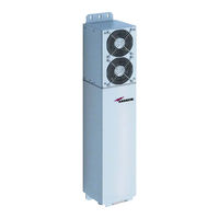
CommScope ION-M7P Manual (46 pages)
Optical Remote Unit, M-cabinet
Brand: CommScope
|
Category: Network Hardware
|
Size: 2 MB
Table of Contents
Advertisement
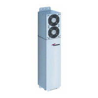
CommScope ION-M7P Manual (46 pages)
Optical Remote Unit, Subassemblies
Brand: CommScope
|
Category: Remote Control
|
Size: 2 MB
Table of Contents
CommScope ION-M7P Manual (51 pages)
Optical Remote Unit
Brand: CommScope
|
Category: Cables and connectors
|
Size: 1 MB
Table of Contents
Advertisement
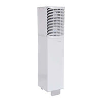
CommScope ION-M7P User Manual (50 pages)
Optical remote unit, ML-Cabinet
Brand: CommScope
|
Category: Remote Control
|
Size: 1 MB
Table of Contents
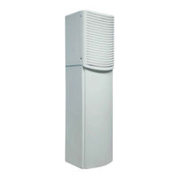
CommScope ION-M7P Manual (43 pages)
Optical Remote Unit, ML-Cabinet
Brand: CommScope
|
Category: Network Hardware
|
Size: 1 MB